Continue to Site

Welcome to our site!

Electro Tech is an online community (with over 170,000 members) who enjoy talking about and building electronic circuits, projects and gadgets. To participate you need to register. Registration is free. Click here to register now.

  • Welcome to our site! Electro Tech is an online community (with over 170,000 members) who enjoy talking about and building electronic circuits, projects and gadgets. To participate you need to register. Registration is free. Click here to register now.

Electronic sound and light module question

Status
Not open for further replies.

Gazzalene

New Member
Hello, I have joined the forum because I know nothing about electronics.
Knowing nothing about electronics is now a problem because my new hobby is Radio control large scale trucks. Just bought my first.
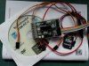
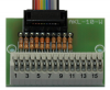
There is a electronic sound and light module that I would love to use BUT the manufacturer presumes you/I know about such!
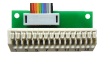
I Have found some vids about the module and would be capable of power connection and programing BUT its the led connection I am really stuck on.
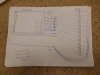
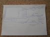
I can not understand schematic drawings and parallel and series confuse me.
I would like to ask here for help.
Firstly what would be the correct section to post in?
Secondly, if I was to post a picture of the module and ask where I should be connecting to and number of leds etc ,would that be rude?
Any advice would be great please
 
I need to find out how to wire led`s to a light and sound module, I will post a picture of the module. I am a complete electronic novice. I only need this because its for a Radio control truck I have just bought. I can solder BUT do not understand circuits,series,parallel or understand schematics. I will also post a hand drawn diagram of how I think its done. In my diagram I have only connected 1 led to each of the 12 outputs. I would need several with 2 leds,for headlights and tail lights etc.
The module has connections down the left side "8" is a +, "9 + 10" are also included as outputs 11 + 12
The bottom left of module has a ribbon cable,this has 10 wires,for 10 outputs.
So a total of 12 outputs for lights can be had.
I hope I have explained this so its understandable?
The diagrame I have drawn I can understand, if anyone has the time to draw a similar one showing 5 single led take offs AND 5 double led take offs I will able to work that out,i think!
Sorry if this is all basic stuff but I really know nothing about this stuff and embarrassed to admit it .
The manufacturer is German so I did not get far with language barrier.
 

Attachments

  • 03.jpg
    03.jpg
    146.8 KB · Views: 93
  • DSCN0695.JPG
    DSCN0695.JPG
    1 MB · Views: 91
The sound/light module has an English language Manual available for download as a pdf from the manufacturer's site.
This explains that the switched outputs are NPN open-collector type, so switch the negative side of any load. The cathode of a LED could be connected to an output. The anode of the LED would connect via a current-limiting resistor to the module's positive supply terminal. Your schematic appears to show the positive sides of the LEDs being switched.
If the module supply voltage (in the 5V-14V range) is Vs, the rated forward voltage drop of the LED is Vf and the desired LED current is I mA, then the resistor value would be 1000 x (Vs-Vf)/I Ohms.
 
Last edited:
Yes I know. But it means absolutely nothing to me. I know nothing about electronics.They have great vids on youtube about the module BUT nothing on connection of leds.
 
Well done alec_t, I have been looking online for a manual but all that I found were for similar modules, and in German (not that that is too big a problem).

Gazzalene, to help you, what we need to know are:
What is the supply voltage to the module?
What LEDs are you using for lights?

With that info it will be easy to knock up a simple wiring diagram to get you, or should I say your truck, going.

JimB
 
JimB, I have found the info.

The power pack for the truck and Module is 6 cell NiMh, 7.2v upto 8.6v freshly charged. The capacity is 5000mah.
The LED bulbs are 5mm and 3mm plastic domed type. the spec says 3.4v , 15-30ma

I do not know if the amount of LEDs is important now? But I would say 14 bulbs max.
Most will need the 2 LEDs on 1 line, headlight/taillights etc.
This module via software can vary voltage to a LED so dipped/main and high can be done by one bulb. they suggest 10% / 30% and 60%
When I understand how to wire a 1 bulb and 2 bulb "line" to the module I can mess about with the options.
I do not know if that "voltage varying" option will need a different resistor to the other "constant" ones.
I do not know if this is all the info needed OR do I need to provide the exact number of bulbs AND 1 and 2 "lines"
Lastly and most important I can not understand proper schematics I need a drawn diagram ,just a rough one like I drew
Many thanks for the help
 
That info is good, if only all those who come here looking for help were so forthcoming with requested information things here would run much smoother.

OK here are the technical calculations:

Assume the LED current is 20mA
Assume the supply voltage is 7.5v

Calculate the LED series resistor
R = (7.5 - 3.4)/0.02 = 205 Ohms
205 Ohm is not a common standard resistor so make it 220 Ohm.

Resistor power dissipation W = 0.02 x 0.02 x 220 = 0.088 W
Any 1/8 or 1/4 watt resistor will work fine.

Enough for now, let me draw a simple wiring diagram.

JimB
 
JimB , even you working out the resistor is a great help.
I was a bit wary posting for help at first. I did not want to seem lazy. I have spent a great deal of time trying to find info on how to do the wiring.I am not lazy.
I will check back after work.
Thanks for taking the time to help me
 
OK, let's try this for a wiring diagram:

Model truck lights wiring.png


Does this make sense?

JimB
 
JimB , even you working out the resistor is a great help.

Some aspects of electronics can be very imprecise and confusing for a beginner.
What I have tried to do in the calculation is to take average values and allowed for a battery which is partly discharged.

JimB
 
JimB, Just on a break so had a quick look. That is just spot on. I do struggle with the line diagrams BUT the 2 sections you did with the methods to use 1 and 2 leds ,make sense to me. Enough so that I feel confident buying a module now £140+ few bit and bobs.

If its ok would you mind if I draw a diagram and post, so you can see if I have grasped it?
Also, now good old Maplins have gone I will have to buy the wire online. What is the thinnest wire I can get away with? and is that single or stranded?

You have been great Jim helping me,many thanks
 
That is just spot on.
Great.

If its ok would you mind if I draw a diagram and post, so you can see if I have grasped it?
Yes, no problem.

What is the thinnest wire I can get away with? and is that single or stranded?
For something which could be subject to vibration, stranded wire is better.
For wire type I would suggest 0.22mm2 (7/0.2, ie seven strands of 0.22mm diameter wire).

JimB
 
Hi JimB, I have drawn up a diagram, Sorry if its simple but this is the only way I can really see and understand it.
I have "tried" to do a single bulb run on output 1 AND a dual bulb run on output 10.
When I use 2 bulb this will be for both sides of the truck so I tried to show a "spacer" wire.
Jim, on the module makers site I found 2 connector blocks that might help me with a neater connection. One has system for the resistors but don't think this will work for the dual bulb runs.
Last question Jim sorry. A lot of this wiring will not be seen. I would imagine a pro would join the leads from outputs at some points for less wiring.
For ease of connections will it be ok to run a wire from every "led run" back to the shared + output? ifs its just a matter of wasted wire and birds nest that's ok.
Many thanks

Gary
 

Attachments

  • DSCN0709.JPG
    DSCN0709.JPG
    808.2 KB · Views: 78
  • Beier%20akl-10.png
    Beier%20akl-10.png
    77.7 KB · Views: 89
  • akl-10-w.png
    akl-10-w.png
    110.5 KB · Views: 80
I have drawn up a diagram, Sorry if its simple but this is the only way I can really see and understand it.
I have "tried" to do a single bulb run on output 1 AND a dual bulb run on output 10.
When I use 2 bulb this will be for both sides of the truck so I tried to show a "spacer" wire.
Yes that looks fine.
I realise that the two LED case is for left and right side of the truck, yes a spacer wire as you put it is fine, in my descrioption I was trying to make things a simple as possible.

I would imagine a pro would join the leads from outputs at some points for less wiring.
Maybe.
For ease of connections will it be ok to run a wire from every "led run" back to the shared + output?
Generally speaking there will be nothing critical about a low voltage, low current application like this. Wire it in whatever way is easiest for you.

JimB
 
That is good to hear, I hope the project goes well.

JimB
 
Status
Not open for further replies.

Latest threads

New Articles From Microcontroller Tips

Back
Top