Continue to Site

Welcome to our site!

Electro Tech is an online community (with over 170,000 members) who enjoy talking about and building electronic circuits, projects and gadgets. To participate you need to register. Registration is free. Click here to register now.

  • Welcome to our site! Electro Tech is an online community (with over 170,000 members) who enjoy talking about and building electronic circuits, projects and gadgets. To participate you need to register. Registration is free. Click here to register now.

Electronic firing system - for fireworks

Status
Not open for further replies.
patrickredmon said:
I have found a great fireworks forum, which also has topics on DIY. I'm not sure if I can post about other forums on here - if someone clarifies I will post a link.

No problem with me!, at least not for such a specific subject.

Moderator.
 
Thanks Nigel
www.pyrouniverse.com

Some of you guys should drop in and have a look. There seem to be a lot of people who are fairly good at this electronics stuff. Better than I am. They definately have the tricks of the trade stuff!

BTW I am looking at modifying the circuit so instead of having individual PB switches, I will have two 6 position selector-switches. That will allow for 36 channels, while still using the 12 core wire. A very clever trick!! I've considered using two 10 position switches, and 25 core cable (100 shots), but cannot find the cable. Makes the wiring a little more tricky, but brings the cost down!!!
 
The igniters I use come from China, when they have fired the LED's in the circuit fade, obviously they haven't blown all the way. When you apply more current they will eventually fade to virtually nothing but there is still a small connection. I think you'll find that most pro ignters behave like this as the only way you should connect igniters is in series so you can perform your test on the whole circuit.
 
Hi,

Came across this topic by chance, but its one I find quite interesting. I'd be interested in taking this a step further and having a microprocessor in the firing unit (in fact the idea being to have a number of firing hubs, with a central controller. Moving a lot of the intelligence into the hub).

From the microprocessor we would need to be able to arm the hub, and detect the continuity of each channel (so it could be reported back to the central station), and obviously fire the channel. I would be looking to be able to switch 12v @ 1A for each channel, but would rather stay with solid state devices than relays.

My initial thoughts on the continuity side would be to have one of the input pins of the processor connected after the current limiting resistor, that way it should read 1 when open circuit, and 0 when connected to a live fuse.

What I would like a hint on would be the best way to fire the pyro. The transistor circuits I am familiar with switch the load from the ground side, but I would have thought thats not good to have live wires around pyros until your ready to fire.

As far as the communications goes it would be a 2 way protocol with error checking etc. I'm not concerned with that at the moment as I find the firmware side of things easy to sort out.

Regards

Ben
 
eblc1388
I was wondering if you could add a short detection to the circuit you gave to patrickredmon. I would like to make it easier to find shorts than having to meter everthing out and hope it stays when I hook it to the circuit.
Thanks eejjr
 
Last edited:
This is a cheap and easy to build system

I have had fun reading through this thread I must say, I have to admit that many people here understand things better then others. First of all the ATF requires that there be a full working safety circuit which is a test mode In the test mode no current larger then 15 mil amp should go to the Electronic Match however the electronic match should complete a circuit thus turning on an LED. This shows the operator that a complete circuit exist. Next and also very important the key should not com out in the power on mode or in the arm mode and the key should be connected to the operator so that he can not leave the panel in these modes (this is for safety) no power no accidental discharge save a life. Another note a properly fired match should never have any way to pass current as it should fully break if they do not you are using too little current to fire them. Here is a nice little one that I made in about 5 hour at a total cost of $125US. it is very fast simple and lens way to making a fully computer control device which cost me about $230us more.

http://www.pyrohouse.com/504cuepanel.htm

All of these parts are easy to find and in expensive.

The 25pair phone cords are very cheap and easy to find at Greybar Electronics
I used a very inexpensive case and it was the most expensive part of mine.
I also did not use the speaker connectors but ones I found that are easier to use quickly and with less fuss also they are easy to use in the dark and give me less issues made by a company called pro clip **broken link removed**

Here is another simple circuit that works great too
http://www.davidavery.co.uk/fireworks/index.htm

I hope that some of this is helpful to any of you that are interested in creating your own system.
 
Wow that launch system for the 504 cue system is pretty nice. I would like to build one but I’m having trouble understanding it. Do the LEDs function when the system is in arm mode too or only in test mode. Also the site shows that you need diodes. I think you need these because the system uses common grounds for each slat. However, were do you put the diodes in the circuit? I guess my problem here is that I’m having trouble understanding the circuit with out a schematic.
 
Here's an overly simplistic schematic. In this model, the LEDs are lit at all times, except when a cue is pushed. See attachment.

In my systems, I use a dedicated power supply (6v) to power the test LEDs. In "test mode" the 6v battery is fed only through the LED circuit. In "fire" mode, the LEDs are isolated from the 24v power source. I did this as an extra precaution, plus it allows me to increase the voltage used to fire without having to worry about it changing the current through the LEDs. Then, to totally overdo it, I added a "push to test" momentary, so even if the switch is left in "test", the LEDs only get powered when the button is held down.

As for the diodes, they are only necessary on systems that use a "grid" or common grounds. They can placed on either side of the speaker terminal or pyroclip where the e-match connects. They really aren't needed except as a failsafe to prevent power from feeding back into the circuit in the rare event an e-match shorts.
 

Attachments

  • 64%20cue%20Wiring%20Diagram.jpg
    64%20cue%20Wiring%20Diagram.jpg
    7.5 KB · Views: 668
This is a nice panel, I do not under stand how you are going to the slats, I only see one plug on the side of your panel.

I would also like to build a panel like this can you help me with the hardware and how to do it.
 
RGC said:
This is a nice panel, I do not under stand how you are going to the slats, I only see one plug on the side of your panel.

I would also like to build a panel like this can you help me with the hardware and how to do it.

Ok im going to atempt to answer you question. The control wire is a 25 pair cable thus giving us 50 wires to use. This system uses a common ground for each slat with 36 channels per slat. There are 14 slats total thus giving us 14 ground wires. So out of the 50 wires we have 36 left. This is where we get 36 channels for each slat. Each of the 14 slats shares the same channels but only the slat with its ground closed through a switch will fire the slected channel.
 
Last edited:
Ok, are all of the 14 slats pluged together and when you put the A switch on it will fire the A slat, or do you have to change cables at the panel for each slat.
 
RGC said:
Ok, are all of the 14 slats pluged together and when you put the A switch on it will fire the A slat, or do you have to change cables at the panel for each slat.

Yes all 36 channels on each slat are paralleled together and when you turn on the "A" switch you are completing the circuit through ground. Thus you don’t need to change any cables.
 
Thank you I under stand how the slats work now. I am not an electrician this is why I am asking the qustions. I am a pyrotech I have been searching on how to build a firing system. I found the panel on here and I would like to build one like this. Do you know if there is a diagram and parts list for this panel.
 
who cant help y want tu build a Sequencer 10 channels every 4 sec must firing a channel my system fireworks firing system gifs a 24 volt output y want to put a power supple 12 volt in the sequincer iff it,s possibel to chance speed of the channels that wil be great

greetings peter dutch fireworker

you cant send your information also by email

vuurwerknfo@xmsnet.nl
 
Firing panels are tricky because they have to be *VERY* safe and reliable. A few things I found along the way that firstly an e-match can be detonated by as little as 10mA, not often, but quite possible with cheaper e-matches that have not been properly dipped or coated. My panel used a few CD40106 with 5v @ 1mA to 'sense' the condition of an e-match. I used 24 volts for my panel because when you fire chains the ignitors are wired in series not parallel, (you may use quick match for waterfalls like I did) and I also used a 'capacitive discharge' method. I had two keyswitch isolators to prevent someone inadvertantly pressing a button whilst you are happily loading an 3" salute into a mortar tube. I used an 8 way rotary switch and 8 press buttons to give me 64 cues down 16 wires and quick release spring loaded connectors.

Hope some of this may be helpful to you.
 
It's been a while since anyone posted to this thread, so I hope I can get a response.

First, let me introduce myself. My name is Ken and I live in Arizona, USA. In the 80's I was part of a professional fireworks team that did large public fireworks displays. Before that, I was an amateur magician that used a variety of flash products in my act. I haven't done much with pyrotechnics over the past 10 years, so I was quite surprised to read about all the new BATF regulations.

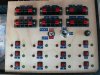
A few weeks ago, I decided I wanted to use flash powder to light up ghoulish decorations in a corner of my yard on Halloween night. My plan was to build a flash pot device with 8 separate pots that would be ignited from a wired in electronic panel. I searched all over the Internet for plans to build such a device and found quite a few, but this discussion was the most detailed that met my needs.

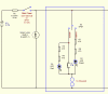
I have started assembling the parts I will need to build this, but have made a few changes to the schematic and was hoping to get feedback about those changes and possibly suggestions for changes I do not even know how to begin making.

I have attached the schematic of my modified circuit.

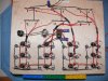
I will be using 9 pin DB connectors to make up a cable that will run from the firing panel to the flash pot array. I am constructing using a roll of surplus wire I had laying around. It has 4 stranded conductors twisted together. I'm not sure but I'd estimate that this is 24 AWG. The completed cable will be about 20' long with soldered 9 pin male DB ends. I thought I'd twist together 4 connectors for the ground, and use 2 connectors twisted together for each pot.

I plan to have three separate flash pot arrays, so I can quickly reset by simply unplugging the spent array and replacing it with a reloaded array. Each load is less than 1/2 a gram of flash powder, so we aren't talking about a major catastrophe if all 8 pots were to fire at once.

As you can see, I have added a Arm/Unarm switch for each of the eight firing circuits. These are mini 3 position SPDT toggle switches with center off (On-Off-On). I think this should more appropriately be labeled "Arm," "Off" & "Test" as the purpose is to be able to individually Arm a single circuit at a time, while leaving all the others either off, or in "Test" mode.

The battery is 12v 1.2AH sealed lead acid. I am making the ignitors fashioned from these instructions I got from another web site. I have attached an image of a completed ignitor from that web site.

I am using a single strand of wire from a braid of picture hanging wire. So far, I have tested about 30 of these and they all ignited fairly quickly, though, at times, there is a slight delay between pushing the 'fire' button and ignition. I'd estimate the max delay is one second.

Am I overlooking anything electronically with this mod? I know it will add to the cost, but I really like the added safety feature of being able to individually arm each circuit separately.

I was hoping to find a way to test the firing panel without hooking up a loaded flash pot device. I was thinking I could make up a DB connector with resistors to represent the ignitors, but know I need to use resistors that will withstand the current. Any suggestions for what these resistors should be? Or, a suggestion for a different way to test the firing panel?

Also, I'd like to eventually modify this so that the 12 V battery is installed on the flash pot array and the firing panel is powered by a 9 V battery. I supposed I could use relays, but I was wondering if there weren't opto-isolators that would work.

Thanks for any help or suggestions anyone can make.

Ken
 

Attachments

  • Fire-Control.gif
    Fire-Control.gif
    16.2 KB · Views: 601
  • igniters_8-finished.jpg
    igniters_8-finished.jpg
    32.7 KB · Views: 435
Glad to see a new post on this thread! I have read through this thread and found it to be a really good source for tips and info on building something like this, which I did. I made a 12 channel fireworks controller with a circuit based on the one discussed in this forum. Thanks to everyone who contributed their valuable ideas and suggestions to this project! Sorry I can't post a link to it yet (first post) but pictures are attached.

Ken, I like your idea to have a separate toggle switch for each circuit, very safe!

In regards to testing the panel:
To test my panel, I hooked up a short length of 2 conductor wire (2 ft or so) to the board, and on the other end just wrapped a strand of steel wool between the wires to use as a test. This way I could make sure the resistor values were okay for the LEDs (to not ignite the wire in test mode) and that the steel wool burned up when the button was pressed. Not exactly the best testing method, but it worked for me!:)

Please let me know if you have any questions about my controller!
 

Attachments

  • 2890710799_44c9489ba2_b.jpg
    2890710799_44c9489ba2_b.jpg
    391.5 KB · Views: 555
  • 2891538536_c60955e30f_b.jpg
    2891538536_c60955e30f_b.jpg
    533 KB · Views: 549
Last edited:
I am using a single strand of wire from a braid of picture hanging wire.
the max delay is one second.

It seems to me switching a capacitor across the wire is ideal for providing very high current for a very short period with average current draw being almost zero.

One reference gives fusing current for a wire as I = kd^(3/2), with k for iron = 3148 and d being diameter in inches, so 40 AWG iron wire melts at 0.5A. No time is mentioned but I think there are Internet sources that do show times.

An unfolded paper clip connected to a car battery takes about one second to melt.

You should be able to tailor ignition delay to whatever you want by using a cap.

https://en.wikipedia.org/wiki/Exploding-bridgewire_detonator
 
Last edited:
fishtx:
Thanks for the reply. That's a nice controller you've got there. Thanks for sharing the pics, they gave me some ideas for my layout and wiring strategy.

I like your suggestion to use steel wool when doing a 'dry run' test of the system. In fact, I think I will build a small 'test' flat out of fiberboard with 8 pairs of sheet metal screws to represent the 8 igniters. Installing those screws from the underside of that board, I can string a strand of steel wool right across the screw points. Since I will be using DB-9 connectors on my control panel and the flats, I will be able to test my DB-9 cable at the same time.

This brings to mind an additional safety feature that I want to incorporate into my working flats. I plan on putting a switch on each flat that will open or close the connection to ground, so that even is a flat is plugged in, it can't be activated until that switch is closed. This might be over kill, but I've seen the effects of 'under kill' and I just don't have the same 'throw caution to the wind' bravado that I did 45 years ago when I started playing with fireworks.

Willbe:

Thanks for your suggestion to use a cap. That brings up my latest challenge.

I finally got all the parts I need to build this baby and I built it on a prototyping board. Everything works great, except for one thing. The igniters don't ignite. The power resistor R2 gets pretty hot, but that's all.

I did make a couple of changes to the circuit.

1) I didn't have a 10 ohm power resistor so I substituted an 8.2 10W resistor.

2) I had a lighted switch that I wanted to use as the main power switch/indicator.

I think your suggestion to use a capacitor is a good one and would solve this problem, however, I don't exactly know how to do that. I assume I'll need a capacitor for each of the 8 firing circuits. In looking at the schematic in the wikipedia reference you gave, I think I'd connect one side of the cap to the battery side of the 'fire' push button. But I have no idea where to connect the other side. And, I don't know what size or type of capacitor to use. I know I probably have a lot of latitude, and years ago, I'd have a parts drawer full of an odd collection of caps to choose from. However, since I am just getting back into electronics, I am starting from scratch. And, since I live in a very small town with no real access to parts other than Radio Shack :-( so I am having to order most everything I need online.

If possible, I'd like this cap to charge when there is an igniter connected and switch 2 is in the 'armed' mode. After the igniter blows, I'd prefer not to be charging this cap.

So, can you (or someone else) please answer these questions regarding using a capacitor for this circuit:

1) What value and type of capacitor should I use?

2) Where should it be connected?

Thanks in advance to all that reply.

Ken

PS. I forgot to mention this, so I am adding it here. I tried disconnecting the incandescent lamp in the switch, but the ignitor still didn't fire.
 

Attachments

  • Fire Control mod 1.gif
    Fire Control mod 1.gif
    21.9 KB · Views: 518
Last edited:
Status
Not open for further replies.

New Articles From Microcontroller Tips

Back
Top