Continue to Site

Welcome to our site!

Electro Tech is an online community (with over 170,000 members) who enjoy talking about and building electronic circuits, projects and gadgets. To participate you need to register. Registration is free. Click here to register now.

  • Welcome to our site! Electro Tech is an online community (with over 170,000 members) who enjoy talking about and building electronic circuits, projects and gadgets. To participate you need to register. Registration is free. Click here to register now.

Electronic firing system - for fireworks

Status
Not open for further replies.
patrickredmon said:
Are you sure this is OK?? It says peak current is 50mA. Am I reading this incorrectly. Sorry for my ignorance!

You're reading the specification correctly. The LED will be damaged if more than 50mA is flowing in it.

But in the schematic, the current is only 11mA for typical LED with a 940 ohm resistor in series powered by 12V. So never could the current exceed a lot more than 11mA.

Don't worry. Tell you what, in the forum if one's calculation is slightly off, there will be a lot of other users offering help to correct it.

All make it better but ocasionally a not so smart guy(you *should* know by now who you are) will make it worse by offering pure bullshits.
 
https://www.electro-tech-online.com/custompdfs/2006/04/1125.pdf

I have finally found a 3 position key switch. This will allow me to have "off" (with key removed), "test" and "armed". It is, however, only rated at 2 amps. It looks to me like the test circuit is not protected by the resistor, hence it could carry more than 2Amp. Is this correct?

Can I simply put the 10W resistor where S1 is, and remove S1 altogether. I would then add the 3 position switch where the 2 position switch is, with the middle position going nowhere.

This would be brilliant as this will only allow the key to be removed in the "OFF" position.

Can you recommend a board to put this all on??
 
patrickredmon said:
It looks to me like the test circuit is not protected by the resistor, hence it could carry more than 2Amp. Is this correct?
It is not protected because the current can never exceed 15mA.

patrickredmon said:
Can I simply put the 10W resistor where S1 is, and remove S1 altogether. I would then add the 3 position switch where the 2 position switch is, with the middle position going nowhere.

This would be brilliant as this will only allow the key to be removed in the "OFF" position.
Yes, you can do that.

patrickredmon said:
Can you recommend a board to put this all on??

I would solder the resistors to the pin of LEDs and the LEDs to the push buttons directly so there is no need to use a separate circuit board to mount the resitors and this reduced the overall wirings. Of course you have to use insulation tubings(e.g. heat shrinkable) of some sorts to get good insulation. I have re-arranged the LED connections in the schematic so that its now easier to wire.
 

Attachments

  • firewk3.png
    firewk3.png
    5 KB · Views: 748
**broken link removed**

This is the URL of a web site selling a 20M serial cable. I am interested in using it to run between my firing panel and the fireworks.

The company does not have any info on it, other than it is rated for 12V.

Do you think it will cope with 1Amp for short pulses?? How much damage could this do? I don't want to use it if it will burn out before the ignightors do!!!
 
patrickredmon said:
This is the URL of a web site selling a 20M serial cable. I am interested in using it to run between my firing panel and the fireworks.

The above cable is a 25-core data cable with very thin copper conductors. It may or may not melt with 1A current through it.

For back yard firework display, there is no harm to try using it. Otherwise use a proper multi-core cable instead. Look inside electrical stores for multi-core alarm cables or even CAT5 Lan cables.
 
Hello everybody, since I am new to this forum I will start by introducing my self. My name is Jason and I am a 20 year old EE major at Texas Tech University. I have been doing Pyro, lights and sound since my freshman year in highschool. I was the pyro guy and my high school hasn’t had pyro since I left. Every thing I know was self taught and learned by reading and experimentation.

Ok here’s my question: patrickredmon what kind of inghitors are you using? Nichrome wire or some kind of electric match or something?
Thanks-Jason
 
I'm using FireDragon ignightors. Not 100% sure of the difference, but I think they are electric match. They are really the only ones available to me.

I thought that cable might be a little on the thin side. Can't find any 11+ core cable anywhere!! Will have to keep looking. Don't want to buy cable that burns out, and then lose the whole show!!
 
I have modified the circuit slightly. What do you think?? Basically I have moved stuff a little so that it is a tiny bit cheaper. Fewer parts per circuit.
Is this likely to cause an issue??
 

Attachments

  • firewk3_modified.png
    firewk3_modified.png
    11.7 KB · Views: 652
Why the 2 470 ohm resistors? you could get away with using 1 1kohm for each. It's also bad practice to use 1 resistor for many LEDs like that. You want to have a resistor for each LED. This is due to the slight differences of the LEDs when they are manufactured, one LED might draw more current than the others, which would cause it to burn out (or drastically shorten its life). You *might* be able to get away with it, but resistors are cheap.
Also, if you wire it like your schematic, the power rating of the resistors will have to be increased to atleast 1 watt.

I dont see the point in having the un-armed portion if you are using the center off key switch, there really wouldnt be a difference between unarmed and off except for the green leds. but thats just my opinion, it'll work either way
 
Usin 2 470 ohm resistors was suggested by eblc1388, although the suggestion was the I use 2 for each LED. I am a newbie to this, so I wasn't sure that it would matter. Hence the post. Thanks for the feedback. I take it that I should stick with 2 for each LED. I think the reason for 2 was incase one failed?
There is a legal requirement that there be a seperate testing circuit and firing circuit. Again, eblc1388's suggestion was slightly different to what I posted. Not sure which is better. I would love to get rid of the 'unarmed' circuit, as it would make the key switch a lot easier to get!! But I HAVE to have it. The 2 'armed' circuits was my idea - an attempt to use fewer resistors. If you think it isn't such a good idea, I will switch back to the original.

I am not sure that this will draw the required 1Amp current. I was talking to a sparky today, and he was showing me some maths to calculate the current. Will this circuit pull the correct current??

:confused:
 
patrickredmon said:
I am not sure that this will draw the required 1Amp current. I was talking to a sparky today, and he was showing me some maths to calculate the current. Will this circuit pull the correct current??

It depends on the load resistance, which we don't know - the 8.2 ohm resistor will limit the maximum current (into a short) to around 1.5 amps.

How about showing us his figures?, although it's probably rare to hear of an electrician who knows ohms law :)
 
patrickredmon said:
Usin 2 470 ohm resistors was suggested by eblc1388, although the suggestion was the I use 2 for each LED. I am a newbie to this, so I wasn't sure that it would matter. Hence the post. Thanks for the feedback. I take it that I should stick with 2 for each LED. I think the reason for 2 was incase one failed?
The resistors are just used to limit the current through the LED, they wouldnt affect the safety of the device. I'd say you would be safe using a 1kohm resistor in place of the 2 470ohm.

patrickredmon said:
There is a legal requirement that there be a seperate testing circuit and firing circuit. Again, eblc1388's suggestion was slightly different to what I posted. Not sure which is better. I would love to get rid of the 'unarmed' circuit, as it would make the key switch a lot easier to get!! But I HAVE to have it. The 2 'armed' circuits was my idea - an attempt to use fewer resistors. If you think it isn't such a good idea, I will switch back to the original.

Well it was more of an opinion really. I just think it would look cooler if you used the 2 switch setup like in the previous schematics.
 
Jeff, do you think Jaycar part RR0572 would do instead of the 2 470 resistors??
In Australia all electricians learn ohms law at TAFE (I am certain). This guy is pretty switched on. I asked him how I would test a wire to see if it would carry 3 amps. He said R=V/I so (if I'm reading his writing correctly), I would need to use a 36W resistor. But he said something about putting 5 20W's together instead. Maybe 4. Can't read the writing. I have no idea!!
Let me just go through the basics, and see if I understand it all. Sorry for my lack of knowledge here!!
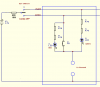
As resistance goes up, current goes down. Hence the 10W resistor. It will drop the current below 3 Amps. Does this depend on something 'drawing' current?? There won't really be anything drawing current. As soon as 1 Amp flows through the ingightor, the circuit will be broken (as the ignightor fires).
The 2 470 Ohm (or 1 1K ohm) resistors are to protect the LEDs from excess current. They should drop the current to about 11 mA. Is that right?
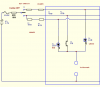
I have put a 3 Amp fuse in the circuit. Now, I think the jey switch is rated at 3 Amps, so I guess I should drop the fuse to 2.5 Amps, so that the key switch won't blow first! But how do I know that there will not be more than that many amps normally, hence blowing the fuse all the time?? Because of the 10W fuse?
If the resistance of the ignighters varies between 1.8 and 2.2 ohms, this will be the equivalent of having a resistor there. If I have a 20M cable to get some distance between me and the fireworks, that will add to the resistance too. Will this be much? I guess it will depend on the cable used?
This is a lot more difficult than I thought!! I am beginning to think I might be better off just to spend the $2500 and buy a professional setup! But I want to avoid it if I can!
Thanks for your help guys!! ;)
 
On a similar subject, I am trying to build around a 16 channel sequencer for firing fireworks, but it’s proving a little more difficult than just a straight firing system. I’ve been looking into using the basic components of a light sequencer and then somehow increasing the current to fire the igniters. I could have up to 10 igniters in series so need a good high current to blow them all.

It needs to be a stand alone box running with an internal 12v lead acid battery.

When a trigger voltage of 24v is sent from the main firing system, the sequencer needs to start its sequence with position 1 firing imeadiatly then a time delay to position 2 and so on firing each igniter in turn with a specific, but adjustable time delay. For example 1 to 16 channels will fire in turn having a 0.25 second gap in between each shot, or one of about 6 other selectable time delays.

It then also needs an output after channel 16 with the same time delay so several sequencers can be joined together.

Any help will be much apprieciated!
 
Mikebang said:
I could have up to 10 igniters in series so need a good high current to blow them all.

It won't work with ignitors in series. Ask yourself a question. If you have 10 one amp fuses in series and you connect them to a 12V supply. How many fuse(s) will blow? Why?

Mikebang said:
When a trigger voltage of 24v is sent from the main firing system, the sequencer needs to start its sequence with position 1 firing imeadiatly then a time delay to position 2 and so on firing each igniter in turn with a specific, but adjustable time delay. For example 1 to 16 channels will fire in turn having a 0.25 second gap in between each shot, or one of about 6 other selectable time delays.

It then also needs an output after channel 16 with the same time delay so several sequencers can be joined together.

The variable timing for individual channel is not easy to do with one shot, logic gates and counters but will be a trivial task using a microcontroller.
 
I'm sorry I obviously wasn't clear... The time delay in between each shot will be exactly the same for that sequence, say 0.25 of a second and all 16 will fire with that delay. But I want to add something maybe a variable resistor so I can alter this time delay to say 0.5 of a second next time I set up the sequencer.

As for the igniters in series this is the only way we use multiple igniters, this is to ensure we can check the continuity in the circuit before firing. It is common practice to wire igniters in this way. Professional igniters are very different than simple fuses as they do not blow completely.

Hope this helps. Thanks again.
 
Mikebang said:
As for the igniters in series this is the only way we use multiple igniters, this is to ensure we can check the continuity in the circuit before firing. It is common practice to wire igniters in this way. Professional igniters are very different than simple fuses as they do not blow completely.

Thanks for the clarification as it was mentioned in previous postings that they became open-circuited after firing. So I guess they still has a ohm or so after firing in order for a string of ignitors to work.

In that case you have to turn off any firing channel after firing and this would make it even more difficult to implement using discrete components.

Off my head one can have different clocking rate selectable using data multiplexer gates. Then connects two 4017 counters together to get the required 16 outputs with logic gates. When this counter chain overflowed then it select another clock rate and moves on to the next 16-output counter arrangement and so on.

As said earlier, a microcontroller or an I/O card connects to a personal PC printer port or serial port would be a much more flexible and easier solution.
 
You dont have to turn of the firing channel after it has fired, as long as it is easily reset. If it stays on at least it will be sure to fire.

Yes I have seen several circuits using the 4017 chip. But would it be able to handle/output around 1amp?

The I/O card idea is another thing I’ve been thinking about, but computer programming isn't one of my best subjects! I have also been looking into a programmable relay box which has about 100 relays in the box, this would be perfect but... relays are a big no no for this type of thing and shouldn’t be used with fireworks in damp fields, and the relay mechanism isn’t the best solution when working with high currents. What else would I be able to use?
 
Mikebang said:
You dont have to turn of the firing channel after it has fired, as long as it is easily reset. If it stays on at least it will be sure to fire.

If you don't turn off individual channel after firing, there will be a current drain of one amp or more flowing. Is that right? The current adds up quickly with additional channels.

Mikebang said:
Yes I have seen several circuits using the 4017 chip. But would it be able to handle/output around 1amp?

No. One would need buffering in form of transistor or relay.

Mikebang said:
What else would I be able to use?

Let's hear from other users of the forum.
 
Hi Mikebang.
I'm interested to hear that your pro ignightors do not fully blow!! The ones I use do - if they light, there is no more circuit. Otherwise it would be silly to have LEDs showing which fireworks have been detonated, as all the LEDs would stay alight!
I have found a great fireworks forum, which also has topics on DIY. I'm not sure if I can post about other forums on here - if someone clarifies I will post a link.
 
Status
Not open for further replies.

Latest threads

Back
Top