Grayhill - 96AB2-102-R - Allied Electronics keypad, non backlight
Jameco Electronics Opto & Illumination: JAMECO VALUEPRO: UN4043-13 EWRS-R 3 digit last score entered
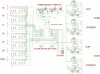
LED's/LCD's - LED Display - 7FR5641BS 4 Digit Current score large display
That's what I've got so far that looks good, not exactly what I wanted but I think they would work.
I've been trying to find a good led for the cricket scoring. I think 5mm leds are too small. I'm trying to find some that houses the led and provides a clear cover lense so as to make it bigger. I'm thinking something like 8-10mm is big enough.
Jameco Electronics Opto & Illumination: JAMECO VALUEPRO: UN4043-13 EWRS-R 3 digit last score entered
LED's/LCD's - LED Display - 7FR5641BS 4 Digit Current score large display
That's what I've got so far that looks good, not exactly what I wanted but I think they would work.
I've been trying to find a good led for the cricket scoring. I think 5mm leds are too small. I'm trying to find some that houses the led and provides a clear cover lense so as to make it bigger. I'm thinking something like 8-10mm is big enough.
")