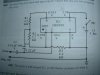
I want to play around with using a signal generator and thought I'd make one using this simple schematic:
C2 is supposed to be a .22uF non-electrolytic. I don't have anything close to that, other than a .22uF electrolytic. Looking at the 3909 datasheet
http://www.datasheetcatalog.com/datasheets_pdf/L/M/3/9/LM3909N.shtml
makes me think maybe that would be ok, with neg. term towards the probe. Can anyone confirm that?
Thanks.
")
")
