Continue to Site

Welcome to our site!

Electro Tech is an online community (with over 170,000 members) who enjoy talking about and building electronic circuits, projects and gadgets. To participate you need to register. Registration is free. Click here to register now.

  • Welcome to our site! Electro Tech is an online community (with over 170,000 members) who enjoy talking about and building electronic circuits, projects and gadgets. To participate you need to register. Registration is free. Click here to register now.

Electrical Power Steering Assist design prob

Status
Not open for further replies.
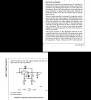
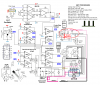
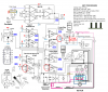
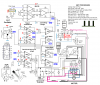
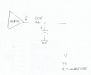
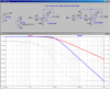
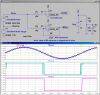
Here is a comparison of two comparators, one without hysteresis, and one with a modest amount of hysteresis. For simulation, I am comparing a simulated slowly varying STEERing signal contaminated with a higher frequency "noise" to 5V. Note the multiple switchings on the NoHYS comparator vs the WHYS one.
 

Attachments

  • Hysteresis.png
    Hysteresis.png
    43.6 KB · Views: 280
Last edited:
Thanks

Here's the latest & greatest on paper, now to build it, test it, hopefully, run it, then maybe, improve with more modern parts, but I do have my proof of concept I that I have been thinking about for quite some time.
Thanks Mike & all
Kinarfi
PS Kind of looking into an H Bridge controller, but they had the drive FETs internal. I'm looking to handle 20 - 40 amp at peak loading.(FYI)
 

Attachments

  • Overs Schematic.PNG
    Overs Schematic.PNG
    38.5 KB · Views: 193
Last edited:
I get that, but why does the gain need to be so high? Is the output of a strain gauge really so low that it needs to be amplified by several hundreds? Opamps that have that much gain are prone to break into oscillations.

I did some observing/testing and when I measured the voltage change of the strain gauge, I got just barely 1mv with lots of torque. I'm now use an INA128 instrument amp and it appears I'm getting a gain of about 3000. I'm still working bugs out.
Thank you Mike for your pointers about singly point ground, must apply to single battery supply also. I keep toasting my LM317 and don't know why.
I guess you might call this a project report. Here's my latest schematic
 

Attachments

  • Steering Schematic.PNG
    Steering Schematic.PNG
    42.2 KB · Views: 237
...I keep toasting my LM317 and don't know why.

Two things:
Is it on a heat-sink?
On the LM317 data sheet, National suggests adding some protection diodes if the filter caps are large. see attachment
 

Attachments

  • 317D.png
    317D.png
    75.1 KB · Views: 249
According to the schematic there are no filter or bypass caps except for the 1000uF on 10V. Is this still the situation?
 
LM317 is on a heat sink, not a heavy one but finned. Will add diodes.
I have 2 filter caps 1 1000uf on the out of the LM317 and 1 10uf on the out put of the INA128.
It was interesting to see the effect of single point ground, and power. With the relays unplugged, measuring mv across the pins 2 & 3 of INA128, the Wheatstone bridge, and using a test light which drew 175 ma, if I touched the drain of FET1, the bridge voltage would change by .4mv, if I touched neg battery, it would only change .1mv, and with a gain of about 3000, that's bad. Then I started working on single point connections and it's looking a lot better. The only thing I can see is what we call line loss on the electrical industry, but with smaller conductors, smaller voltages, and more sensitive equipment, it does become a factor.
On this drawing I used blue as the negative on the control side and black on the power side, Red for +10 volt on the control side and off red for the 12-14.6 of the battery.
Thanks
Kinarfi
 

Attachments

  • Steering Schematic.PNG
    Steering Schematic.PNG
    42.7 KB · Views: 198
I added 4 Protection Diodes (on paper) to the LM317 on this drawing, PD1 - 4. Are any of them a bad idea or even a good idea, particularly PD 3 or 4, in red circle?
I plan to pull power from the battery for the control circuit on 2 #16 wire and pull separate wires for the power, probably 1 #10 + chassis ground.
Any other ideas? And thanks!!!!!! A lot.
Kinarfi
 

Attachments

  • Steering Schematic.PNG
    Steering Schematic.PNG
    43.8 KB · Views: 173
It's strange, when you're working on a project and when ideas or inspiration or when you realize you screwed up happens, like at 12:30 a. m. Any way, the circuit seemed to be doing fine except for ccw rotation. Then while looking at the drawing, I realized my hysteresis feed back wasn't right, So I changed it (on paper) and circled it in red and also a capacitor I plan to add.
Here's the latest & greatest for your perusal.
Thank you,
Kinarfi

I'm adding back EMF diodes and capacitors to motor relay, I would appreciate any comments as to what value caps would be about right, I plan on using .1µf or any other help offered.
Thank again,
Kinarfi
I changed Drawings also
 

Attachments

  • Steering Schematic.PNG
    Steering Schematic.PNG
    45 KB · Views: 252
Last edited:
One other thing. I notice that there is no bypass cap on the input of the LM317. You should have ~5uF there. See the LM317 data sheet for recommendations.
 
No comments, Just my latest drawing.
 

Attachments

  • Steering Schematic.PNG
    Steering Schematic.PNG
    44.6 KB · Views: 149
Last edited:
Move the wire that takes the Strain signal down to the four comparators to the junction of the 50k and 2uF capacitor.

Also, add an input cap on the LM317. It is required if the wires going to the battery are more than a few inches long.
 
...
Link to schematics and changes, Newest first, and some Scope captures.
...

You still haven't fixed the "filter" on the output of the INA. Reread my previous post.

It should look like this:
 

Attachments

  • Filterfix.png
    Filterfix.png
    91 KB · Views: 158
Last edited:
Thanks Mike, Got it, I also put 1uf between 3 and 8 of the INA128 Which killed some oscillation I was getting.
**broken link removed**
Hysteresis calculations are fun, turns out what works well for OP5 doesn't work so well for OP6 because it's working at a lower voltage, then after it has flipped, it's working with a higher voltage, and while approaching the flip point, the hysteresis value is also changing. I'm quite happy with what I have now,
Thanks Again
Kinarfi
 
Last edited:
You still haven't fixed the "filter" on the output of the INA. Reread my previous post.

It should look like this:
This appears not to work, the 50K ends up being in series with the hysteresis resistors of OP5&7 and had a voltage drop 1.335 static and varied from .8 to 1.9 v
 
Ok, I forgot that two of the comparators are "inverted", and they required a buffered signal.

Here are two different versions of a proper low-pass filter with 10Hz cutoff:
 

Attachments

  • LPFs.png
    LPFs.png
    47.9 KB · Views: 159
**broken link removed** **broken link removed** Green trace is TP2, Yellow trace is set point.
My latest problem was the relay controlled by OP6 chattering when it first turns on, this doesn't happen with the relay controlled by OP5. The reason OP6 chattered was because of the spike on TP2 which coincided with the turn off of FET4 or 5. On OP5, TP2 rises above the set point and the spike is upwards, so it does not effect the output. On OP6 TP2 falls below the set point and the spike goes back above set point, turning OP6 off momentarily, I compensated for this with a larger hysteresis and an inductive filter, now I don't have the problem. If you have any suggestions or comments, I would certainly like to hear them.
Thanks for all the help, Especially Mike,
I'll report back after installation and testing.
Kinarfi
**broken link removed**
 
Last edited:
Changed the design some

Changed my design a bit and my question is; is there any reason NOT to remove the 10 volt regulator from my circuit. The power comes for an automotive alternator, the same as any modern car. I am still keeping the high current area separate from the controlling area and separating them with a diode in the + line. I see no need for the 10 volt regulation for the controller. The removed regulator circuit is in green.
Thank You
Kinarfi
 

Attachments

  • post.PNG
    post.PNG
    57.2 KB · Views: 247
Status
Not open for further replies.

Latest threads

Back
Top