kinarfi
Well-Known Member
**broken link removed**
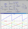
This design looks good on paper and on the bench, as long as I don't load the FETs, that is connect the drains. When I get this all tuned and balanced, I get a scope picture like this,
**broken link removed**
This is TP 9 & 10. TP2 should be a smooth line at 5.00 vdc and it is, but when I connected a resistive load to the Power FET driven by OP7, I got this on the scope, Yellow trace, Green trace is the saw tooth I use to create my pulse width output.(no torque on steering wheel)(and only one FET connected)
When I apply enough torque to the steering wheel to get the Pulse width to 100%, TP2 goes flat and smoother again.
My apologies if this is double posting, but I still have a problem. I'm planning on changing the Wheatstone bridge amp when I get the IC, Maybe that will fix every thing.
Does anyone have any suggestions on understand why TP2 distorts,
Thanks,
Kinarfi
Attachments
Last edited:
 2 they are superglued to the steel shaft and sense the stress of the steel as strain (torque) is applied by stretching or contracting with the surface of the steel
 and if I remember correctly, the change in resistance is .7 ohm max, it may have been .7 miliohms, I'm checking.