Continue to Site

Welcome to our site!

Electro Tech is an online community (with over 170,000 members) who enjoy talking about and building electronic circuits, projects and gadgets. To participate you need to register. Registration is free. Click here to register now.

  • Welcome to our site! Electro Tech is an online community (with over 170,000 members) who enjoy talking about and building electronic circuits, projects and gadgets. To participate you need to register. Registration is free. Click here to register now.

'Electric fence' warning buzzer and lights

Status
Not open for further replies.

ESchreiber

New Member
Hello, newbie poster here. Glad to find what looks like the perfect resource for what I need!

I used to play with electronics circuits in high school, and was moderately good at laying out circuit boards given a schematic. But that was in 1984. Fast forward a quarter century, and I think I might still remember which end of the soldering iron to plug in. Maybe. It's been a long while.

Still, that long-ago experience makes me the closest thing to an electronics expert in the family. So I have been given an assignment to complete a toy for my nephew.

He loves the movie Jurassic Park, and is always talking about electric fences and keeping the dinosaurs contained. So his grandfather has built him a 2x2' octagonal board with pylons and cables and such, to be the 'electric fence' around his dinosaur collection. It's really cool (makes me wish I was a five year old kid again). My job is to wire it with lights atop the pylons, and a warning buzzer.

What I'm envisioning is something where my nephew pushes a button or throws a switch, and the following happens:

- Red lights (LED) flash perhaps five times, approximately once per second
- A buzzer sounds in sync with the flashing red lights
- Green lights come on, red lights and buzzer stop, indicating that the fence is now 'live'.

The fence won't actually be electric, of course (though I pondered giving it a little bit of zap. I figured with a couple of AA batteries and a relay wired as an interrupter, I could get a mild shock going). Wisdom, for once, has prevailed :)

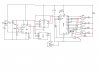
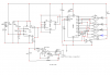
Anyhow, I suspect the circuit I need for the lights and buzzers would be pretty simple, but all my knowledge of designing such things is long gone. About the only thing I remember is a 555 timer, and I don't know if they even make those any more!

I would be grateful if anyone could direct me to a circuit design that would do the trick, or even a couple of circuits that could be clumped together to do the job. I'm fairly confident that given a schematic I could hack together the actual finished product.

Thanks in advance!
 
Hi,

if you are satisfied with three flashes and three beeps here is a simple circuit for you.

Creating more than three flashes will require two cascaded decimal counter ICs.

The buzzer is a self contained type with a built in oscillator circuit.

Boncuk
 

Attachments

  • TOY-E-FENCE-SCH.pdf
    30.1 KB · Views: 934
Last edited:
Thank you Boncuk, that may well do the trick!

So, did you just sit down and whip this plan up off the top of your head? If so, color me impressed, and grateful!

I'm pleased to report that despite the 25 years that passed since the last time I played with electronics, the schematic made pretty good sense to me. I'm going to try to get my hands on the parts and breadboard the circuit this weekend.
 
Last edited:
Hi ESchreiber, (typical american name :) )

I suppose you don't want to make the final design on a breadboard.

Thinking ahead I've also designed a PCB layout for you.

Just PM me to obtain the Eagle files. The layout is pretty rugged and should work properly even if handled roughly.

I've added a pot to set the speed from 1Hz to ~0.3Hz. (just in case the beeps are too short. :D )

Boncuk
 

Attachments

  • TOY-E-FENCE-SCH.pdf
    38.1 KB · Views: 600
  • toy-e-fence.gif
    toy-e-fence.gif
    31 KB · Views: 1,231
  • toy-e-fence-silk.gif
    toy-e-fence-silk.gif
    21.1 KB · Views: 2,177
  • toy-e-fence-solder.gif
    toy-e-fence-solder.gif
    20.4 KB · Views: 1,538
Hi ESchreiber, (typical american name :) )

It's been a busy week, and I was flat out of creativity :)

I suppose you don't want to make the final design on a breadboard.

No indeed - not for a five year old's toy! The final build is going to be mounted inside the sturdy wooden base of the toy, where destructive little fingers hopefully won't be able to get at it.

Thinking ahead I've also designed a PCB layout for you. Just PM me to obtain the Eagle files. The layout is pretty rugged and should work properly even if handled roughly. I've added a pot to set the speed from 1Hz to ~0.3Hz. (just in case the beeps are too short. :D )

Thank you very much! No need to send the Eagle files - I don't have the application, and I've got waaaay too much software to deal with already. The GIF files you attached should be more than adequate.
 
just read and thinking basically same but

why not slow the clock down (555) then connect to every other output of the 4017 and have 4 red leds then have the green led connected to pin 2 and 4 with pin 15 tied to pin 3 for halt
OR
throw in a flip flop and divide by two then cycle the leds randomly or round n round or ??
this could be fun
 
here is my interpertation

this will flash the LEDs in order 1,2,3,4,1,2,3,4 at approximately 2 second rate
while buzzer is pulsing at 1.3 hz
might speed up clock (add pot to 555 circuit for adjustment)
lots more action but more parts
basically same as Bocuk but clock is divided by two and output LEDs flash separately
yo Boncuk = why the D6 diode??
I'm thinking the buzzer reverse flux??(think similar to relay??)
could use a 556 and connect speaker as a siren using second half. Parents would appreciate that.
 

Attachments

  • jurasic park.PNG
    jurasic park.PNG
    29.9 KB · Views: 894
Hi, I'm glad that wisdom prevailed. It would be cruel to shock a child. It dawned on me, however, that if you could implemet a small, mechanical vibration on the wire, it would give a safe sensation. You could use a small DC motor with an eccentric to produce the small vibration.
 
Last edited:
Hi, I'm glad that wisdom prevailed. It would be cruel to shock a child.

It'd be cruel to do it forcibly, but I had been thinking more along the lines of something he could turn on or off himself. It would have been up to him if the fence was live or not, and the shock would have been quite small (and driven by AA batteries only). I know that when I was a kid I'd have loved it! Maybe I was a weird kid, though.


It dawned on me, however, that if you could implemet a small, mechanical vibration on the wire, it would give a safe sensation. You could use a small DC motor with an eccentric to produce the small vibration.

That would be cool, but our wires aren't really tight enough to make that work. The structural integrity requirements for that would have been rather a lot of engineering for something designed to hold plastic velociraptors :)
 
you want this project to vibrate

an electric motor with an unbalanced flywheel.
have each corner of the platforn mounted with a short coil spring that supports the entire platform.
when the LEDs start flashing, the electric motor comes on and entire platform shakes like an 8.0 earthquake (depending on spring stiffness)
of coarse have a second plywood platform under main platform to mount the other end of the springs.
with this arrangement it wouldnt take much to shake the dinos to the point of falling over.
LOTS of action for sure
 
yo Boncuk = why the D6 diode??
I'm thinking the buzzer reverse flux??(think similar to relay??)
could use a 556 and connect speaker as a siren using second half. Parents would appreciate that.

Nope, I don't think similar to relay. I think more of interference caused by the oscillator circuit in the buzzer.

I used a self contained buzzer because they are cheaper to buy than sounders.

Concerning the sound of a siren it reminds on a Christmas gift I gave to my son. It was a drum. On New Year's eve I gave him a pocket knife to find out where the drum's sound originated from. :)

Further I intended to make a little add on for a toy, not a monument consisting of ICs.

Boncuk
 
Concerning the sound of a siren it reminds on a Christmas gift I gave to my son. It was a drum. On New Year's eve I gave him a pocket knife to find out where the drum's sound originated from. :)

The parent in question is my sister. I find that I am unconcerned about any noise the thing might make :D
 
go for about 50 watt amp

that should really make an impression--lol
be nice to get your hands on a SN76488N sound generating chip
lets see an LM383 8 watt amp would do the deed unless you want MORE POWER go with a 16watt bridge amp using 2 of the LM383's
A circuit board could be designed and etched (one is already posted but only has one LED.
been playing w/ design using the schematic I posted.
how big of an amp?? desired.
 
The parent in question is my sister. I find that I am unconcerned about any noise the thing might make :D

:D Piezo-sounders normally make 85db, which get quite impressive after a while. Have fun. :D

Boncuk
 
same but w/ 8watt amp

same circuit but removed 1/2 of the flip flop, added an LM383 8 watt amp
 

Attachments

  • jurasic park2.PNG
    jurasic park2.PNG
    34.1 KB · Views: 1,371
Followup

I don't like when folks show up, get what they want, and disappear, so I figured I'd drop in for a followup.

First, I had to do a bunch of research to find out what the various notations for the design that Boncuk provided meant. I had no idea anymore what 47 uF/16 or 6K8 meant. So I lurked around here and searched resources on the net, and learned what I needed.

Then I blithely went off to Radio Shack to purchase the parts. Ooof. Radio Shack isn't what it was when I was a high school electronics hobbyist 25 years ago! I bought an assortment of parts, but not nearly the full set of what I needed - just the diodes and most of the resistors.

So I came back here and looked for names of online parts suppliers that would deal with tiny lots like I needed. I found DigiKey Corp. | Electronic Components Distributor | United States Home Page, and they had almost everything. All they didn't seem to have was the etchant solution (unless I wanted to get into some high-end photographic setup) and the dry transfers for laying out a board. I'll be taking all the parts I got at RS back this week. Digikey had much better prices. How do they stay in business? Surely it cost them more than 29 cents to have someone pick resistors five at a time!

Anyhow, all the parts arrived in about 3 days - nice! I headed off to the local Fry's electronics store for the etchant (which they had) and the dry transfers (which they didn't). I'm coming down to my deadline here, and didn't want to get stalled for lack of transfers. But a solderless breadboard caught my eye, and I abandoned my fancy etched PC board notions.

So finally this weekend I sat down and built the circuit on the breadboard. No doubt you guys are experts who could have whipped it up in 30 minutes or so, but I muddled with it for several hours. I'm very anal retentive, and I wanted everything nice and tidy. And, I admit, I was having fun - it has been far too long since I played with this sort of thing!

Tonight I jury-rigged the push-button switch. I admit that I had no expectations that it would actually work. Far too many opportunities for failure - picking the right parts, connecting the circuit correctly, pointing the diodes and caps in the right direction, etc. I attached a battery and...

I'll be damned. It actually works! Exactly as Boncuk described. I now have three evenings to assemble the circuit into the base of the toy (away from prying hands). I'll have to look up if LEDs are supposed to be in series or parallel, since there are 8 of each color ranged around the top of the electric fence.

Anyhow, I wanted to drop in and say thanks to everyone for the discussion and this most excellent website and community, and thanks especially to Boncuk for the plans!
 

Attachments

  • electricfence.jpg
    electricfence.jpg
    318 KB · Views: 933
Last edited:
leds should be in series
a good cheap etchant is 1 part muratic acid, add to acid 2 parts hydrogen peroxide
not as messy as the brown etchant. you can see your progress.
For this simple circuit RS sells several proto boards that could be used but an actual pcboard is better.
after all is working be sure to spray a protective coating to prevent oxidation.
 
I'll have to look up if LEDs are supposed to be in series or parallel, since there are 8 of each color ranged around the top of the electric fence.

Glad the circuit is working. However you can't connect 8 LEDs in series using a 9V battery.

All you'll see is dark LEDs connecting 8 in series.

Here is a revised schematic. Connect three strings of LEDs in parallel, two of them containing 3 LEDs and one containing 2 LEDs.

Please note the changed values of current limiting resistors. The resistors are calculated for a forward current of approximately 10mA for longer battery life time.

Regards

Boncuk
 

Attachments

  • TOY-E-FENCE-SCH.pdf
    49.8 KB · Views: 439
Last edited:
I'll have to look up if LEDs are supposed to be in series or parallel, since there are 8 of each color ranged around the top of the electric fence.

Glad the circuit is working. However you can't connect 8 LEDs in series using a 9V battery.

All you'll see is dark LEDs connecting 8 in series.

Here is a revised schematic. Connect three strings of LEDs in parallel, two of them containing 3 LEDs and one containing 2 LEDs.

Regards

Boncuk
 
Last edited:
Status
Not open for further replies.

Latest threads

New Articles From Microcontroller Tips

Back
Top