Continue to Site

Welcome to our site!

Electro Tech is an online community (with over 170,000 members) who enjoy talking about and building electronic circuits, projects and gadgets. To participate you need to register. Registration is free. Click here to register now.

  • Welcome to our site! Electro Tech is an online community (with over 170,000 members) who enjoy talking about and building electronic circuits, projects and gadgets. To participate you need to register. Registration is free. Click here to register now.

electric fence charger of ~100mj

Status
Not open for further replies.

g2c

Member
Hello,

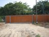
My cat, Dingi, has learned he's able to jump 1.8meter above the yard fence :mad:and to go out which is very bad particularly because of the cars driving fast in the road adjacent to the yard.

I want to make an electric fence ~20 cm before the foot of the fence at say 20 cm above ground which should prevent him from jumping. I saw in Marc's Technical Pages: Low Power Electric Pet Deterrent a circuit which is claimed to produce < 100mj though my maths gives .5*(2*10^-6)*(250^2)~6mj. I did not fully understand the circuit, for me it appear to make 50Hz pulses and not a steady dc voltage as is the case for horse fences:confused:

Also it is difficult for me to run the a 220V wire from the house to the entrance (~40m) so I prefer a solution with a 12V battery which I could place in a waterproof box near the physical fence. I would appreciate very much any help you could give me to build this charger

Thanks in advance from Dingi & me

Guy
 
Just a rough guess leads me to the conclusion that your smart cat will have learned to jump a way to avoid your exceptionally weak e-fence within two or three days.

Better put the wire up to top and about 10cm inside the fencing, which will be a 100% hit when jumping up.

Here is a schematic using a car ignition coil. The power output depends on the pulse length and with the given values the minimum power is 250mJ at which the circuit uses an average of 25mA.

Boncuk
 

Attachments

  • E-Fence.gif
    E-Fence.gif
    21.9 KB · Views: 13,505
Thanks Boncuk,

I am afraid that my cat hurt himself if the wire is tied at the top: He might even choose to continue and land in the other side and avoid to come back :( Also it'd be difficult to ground the the fence.

If I understand, C4 charges through the R1 R2 R3 combi according to S1 and S2 and discharge through D2, so the 555 output low duration is constant and the high duration is adjustable and as a result the switches adjust the 555 frequency; is this correct? Can you please tell what are D3, R4 R5 for? And also D6?

Thanks again

Guy
 
Thanks Boncuk,

I am afraid that my cat hurt himself if the wire is tied at the top: He might even choose to continue and land in the other side and avoid to come back :(

I've not experienced any animal jumping at a charged wire - which is an obstruction, additionally loaded with HV - to continue.

Cats are a special species of animals. They don't obey like dogs do and just want to be left alone until they feel they need to be hugged. They must learn the hard way concerning freedom.

Also it'd be difficult to ground the the fence.

If I understand it right every fence starts somewhere near the ground. Of course a wooden fence wouldn't make sense to ground it. I just assumed it's a metal mesh fence.

If I understand, C4 charges through the R1 R2 R3 combi according to S1 and S2 and discharge through D2, so the 555 output low duration is constant and the high duration is adjustable and as a result the switches adjust the 555 frequency; is this correct? Can you please tell what are D3, R4 R5 for? And also D6?

The entire R/C combination around trigger and threshold pins is a PWM circuit (therefor D2 and D3) taking care of long pulse pauses with short variable pulse widths. R1 through R3 determine the pulse width being 16.5, 24 and 31ms while the time between pulses is constant at 1.5 seconds. Energy levels are 250, 400 and 450mJ. You might want to change to 1 pulse per second by shorting R5.

D6 - together with C7 and C8 decouples the IC from battery power. If the battery is almost depleted the voltage drop would cause succesive resets of the timer, hence increasing frequency.

A dual switch is used for the reason of better function in free air where contacts might corrode easily. Looking at the connections of S1.A and S1.B (no such thing as S2) you will notice that they are connected parallel.

For C4 I recommend to use a WIMA MKT type capacitor. The ignition coil should be designed for electronic ignition systems with a primary coil resistance of 0.7Ω and an inductance of 5mH.

Thanks again

Guy
 
Hello Boncuk,

While reading your question regarding he fence I realized that Dingi has 'only' to jump 1.65m and that he knew he would lend on a comfortable surface of the iron structure **broken link removed**. So you were right and your solution of an upper wire can work too but I don't have the courage to try it.

Back to the circuit, I think that now I understand: when the output is low, D2 is blocked and D3 is slowly discharging C4 via ~1.4MΩ. once TR is attained, the output goes hi, D2 is conducting and charges C4 quickly via R1 (+R2 (+R3)) until THR etc. And if the high period is increased by adding resistors, these are subtracted during the low period so as to have a constant frequency. Bravo!

Now two questions for the weekend :)

1) How do you derive the power from the recurrence and the hi pulse width?

2) How would you recommend that I realize the circuit?

Regards,

Guy
 

Attachments

  • doorway annotated.JPG
    doorway annotated.JPG
    2.8 MB · Views: 1,986
Cats are pretty clever when it comes to satisfying their need to breed, usually a vet would be the most helpful in this. Even a surgically altered cat will wander occasionally, but doesn't go to a lot of trouble to gain freedom. If the can't get over a fence, they will look for a way under or through. They make a mad dash for open doors or gates. I don't know why some cats learn to stay out of busy streets (mine), or why some lay down right in the middle (a neighbor's), but they are easily replaced...
 
Now two questions for the weekend :)

1) How do you derive the power from the recurrence and the hi pulse width?

I calculated it on the basis that 3.6MJ equals 1KW/h

2) How would you recommend that I realize the circuit?

You certainly wanted to know how to install the fence. I'd use iron strips of at least 1.5ft lenght and mount them on the already present iron work at an angle off the vertical line of approximately 30degrees.

Use three wires at equal distance of which the first (bottom) should be connected to earth (as your circuit ground should be) and the two other should be the hot wires (carrying HV). Use commonly available ceramic isolators.

To connect the cables to the sliding gate I recommend using a spring loaded reel and "Litz" type (stranded wire) cables to have them tidy.

When jumping up the cat will touch either of the hot wires and searching for something to kick himself up he'll hit the earth wire with the rear feet.

I know it sounds brutal, but it is the only safe way to keep your cat inside the garden and not be crossed by an 18-wheeler. If had the choice I'd select a short pain instead of death. :)

My two tomcats had both surgery (self made) and are not interested in girls anymore. They avoid the road and stay in the garden without fence.

Regards,

Guy

Regards

Boncuk
 
Hello Buncuk,

Dingi was sterilized when he was 6 month.

During the day, when I am in the farm, Dingi stays by me and help me in my work. As I don't stay here at night, he goes out to the neighbor's house, over the street. Perhaps just to stay near some company. I was thinking of having another cat or a rabbit but I am not sure yet.

No I asked how to make the circuit physically. When I was young (long ago) I used to make small prototypes on Vero boards with wire wrap but I don't know if this the way to follow today. I remember also using solderless board (think these are called breadboards)

You mean 3.6MJ=1KW*H ok but I don't see how do you get the 250, 400 and 450mJ values

Regards

Guy
 
Hello Buncuk,

No I asked how to make the circuit physically. When I was young (long ago) I used to make small prototypes on Vero boards with wire wrap but I don't know if this the way to follow today. I remember also using solderless board (think these are called breadboards)

Here are the layout and the silkscreen. Don't ignore the wire jump (drawn red on the component side). For the Eagle files PM me.

You mean 3.6MJ=1KW*H ok but I don't see how do you get the 250, 400 and 450mJ values

I think I'm not supposed to teach you math. :)

Regards

Guy

Regards

Boncuk
 

Attachments

  • E-FENCE-BRD.pdf
    36.3 KB · Views: 1,184
  • E-FENCE-SILK.pdf
    29.4 KB · Views: 1,111
You mean 3.6MJ=1KW*H ok but I don't see how do you get the 250, 400 and 450mJ values

By definition, 1J = 1Ws (1 watt-second), which is how Boncuk derived 3.6MJ = 1kWh. The the conversion from watt-second to kilowatt-hour is simply a matter of dividing by 3,600,000 (1J = 1/3,600,000 kWh or 3.6MJ = 1 kWh). If you're not familiar with simple equations, you should learn / revise this before attempting an electronics / electrical project.
 
Last edited:
Well, I just noticed that 3.6MJ was 1KWH and not as mistakenly written 1KW/H. Thanks anyway
 
Hello Boncuk,

I have finished to mount the circuit and before I actually put it in place, I need to derive the energy vs. the pulse length. I assume my coil has the parameters you asked i.e. 0.7ohm, 5mH,

Using the current establishment rate I=Imax(1-exp(-t/(L/R))) and the energy stored for a current I: E=.5L*I^2


I find the following theoretical values
pulse (ms) Energy (mj)
16.5 600
24 680
31 720

Please help me find what is wrong?
 
Hi g2c,

you probably didn't take into account any losses.

I also don't know which values you used.

Boncuk
 
Status
Not open for further replies.

Latest threads

New Articles From Microcontroller Tips

Back
Top