Continue to Site

Welcome to our site!

Electro Tech is an online community (with over 170,000 members) who enjoy talking about and building electronic circuits, projects and gadgets. To participate you need to register. Registration is free. Click here to register now.

  • Welcome to our site! Electro Tech is an online community (with over 170,000 members) who enjoy talking about and building electronic circuits, projects and gadgets. To participate you need to register. Registration is free. Click here to register now.

Electret mic and phone for heart and lung sound for telemedicine

Status
Not open for further replies.

doldett

Member
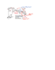
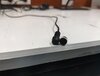
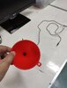
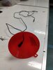
Hi, my friend and I had tried combining lavalier mic and funnel as DIY stethoscope connecting to phone for telemedicine. During a video call, the heartbeat can be clearly heard from the headset but not the lung sound. I think if the signal from lavalier mic can be amplified it would lead to better sound for doctor to analyze, especially the lung, as covid patients in home isolation in my country are suffering and dying from lung infection.

I have come across threads discussing electronic stethoscope in this forum, but the output is used to drive a headset or speaker, which is different to driving trrs jack.

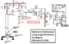
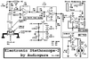
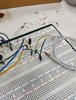
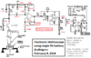
I am planning to implement two schematics from audioguru (one with 9 V and another with split supply). I am wondering if i can use one of the schematics to my project. At the moment, I would prefer the circuit with single 9 V battery. Please advice me on the following questions.

1. Do I need power amp (lm386)?
2. if i do not need power amp, i guess i have to increase the gain of the first stage amp. Am i correct? how much gain would need to be increase?
3. OPA2134 suggested by audioguru is rather expensive. Can i instead use njm5532?

Many thanks in advance.
 

Attachments

  • electr. steth 9V.png
    electr. steth 9V.png
    24.8 KB · Views: 436
  • Electronic_Stethoscope_2 schematic.png
    Electronic_Stethoscope_2 schematic.png
    7.3 KB · Views: 385
You should be able to take the output from the R11 volume control and still get a lot of gain. Start with it all the way down and increase gradually while listening.

Tip: Add a diaphragm across the open end of the pickup "funnel" - and keep the internal size of that small, so a given diaphragm movement causes a higher pressure change at the mic. Something like a bottle top may work well.

The diaphragm could be permanent, something thin and flexible like very fine brass foil, or a piece of kitchen "stretch wrap" / cling film type stuff, stretched tightly. It means a perfect seal to the skin is not needed and small movements (sounds) are picked up better, than with an open end.
 
I fixed that circuit 17 years ago. It has a high frequency cutoff at 80Hz to hear low frequency heartbeats.
In my circuit I used a plastic bottle cap to hold the mic. The cap blocks some background sounds..
If the filter capacitor values are reduced to make the high frequency cutoff at about 2.5kHz then lung sounds can be heard.
An NJM5532 dual opamp can be used. It is not powerful enough to drive some low impedance headphones.
 

Attachments

  • heartbeat and lung sounds.png
    heartbeat and lung sounds.png
    44.7 KB · Views: 331
Many thanks rjenkinsgb and audioguru for your advices. I will go ahead and order passive components to prototype circuit on the breadboard. I do have some question about components please advice me as well.

1. when i search for lm386 it shows two version lm386N-1 and lm386N-3. Should i go with lm386-3 because higher output power?
2. I had read it somewhere that film capacitor (polypropylene) is generally used in audio amp. However, in the circuit with 9 V showing all polarized capacitors, should i buy only electrolytic cap? is 25V rating cap enough?
3. Can i use all carbon type resistors or they have to be metal type?
 
This might help with some of the front end boost from the electret mic. This circuit mod adds about another x100 Gain to the Electret mic
 

Attachments

  • electr. steth 9V v2.png
    electr. steth 9V v2.png
    49.8 KB · Views: 324
I do not know why they make an LM386-1 and an LM386-3 amplifiers because they are in the same package, have the same recommended maximum supply of 12V and cost the same. The difference in output power of 250mW min with a 6V supply and 500mW min with a 9V supply is when they are both clipping and producing horrible distortion. Doubling the level sounds only a little louder.
Do you have 40 years old 8 ohms headphones that need a power amplifier? Most headphones today are 32 ohms but the two earphones in parallel made 16 ohms. An LM386 powered from 9V and with a 16 ohm load produces only 300mW total with low distortion and will be extremely loud.

If you drive a loudspeaker then you will have acoustical feedback howling because the mic is very sensitive and it will hear the speaker.

Only high capacitance capacitors are electrolytic, 25V is fine and are polarized. The nF capacitors are inexpensive polyester or mylar type film and mine are 5% tolerance and 63V. I used huge and expensive polypropylene capacitors 55 years ago in a vacuum tubes amplifier.

The circuit with the two 9V batteries used an older TL072 dual audio opamp that does not work when a 9V battery drops below 7V. I used the TL072 to replace original antique 741 opamps that were very noisy and did not work with less than 10V. Your idea to use an NJM5532 dual opamp is fine with only a single 9V battery because it works down to 6V.
 
Do you have 40 years old 8 ohms headphones that need a power amplifier? Most headphones today are 32 ohms but the two earphones in parallel made 16 ohms. An LM386 powered from 9V and with a 16 ohm load produces only 300mW total with low distortion and will be extremely loud.
audioguru, I am not planning to use any headphones.

I wanna use your designed circuit to drive trrs jack, which will be connected to phone for telemedicine. I guess from the rjenkinsgb post the lm386 is capable of doing that.

Only high capacitance capacitors are electrolytic, 25V is fine and are polarized. The nF capacitors are inexpensive polyester or mylar type film and mine are 5% tolerance and 63V. I used huge and expensive polypropylene capacitors 55 years ago in a vacuum tubes amplifier.

Only electrolytic and polyester capacitors used in the circuit then. Is 0.1 uF considered as nF cap? So I need to order 1000uF, 100uF, 47uF, 10uF, 1.5uF electrolytic capacitors and 470nF, 330nF and 1.5nF for polyester capacitors.

What about 0.1uF? should it be electrolytic or polyester? Anyway, thanks audioguru you have save me from ordering ceramic cap ^^.
 
A phone has a microphone input. Then the LM386 power amplifier is not needed. The volume control output will need a series capacitor to block DC from the phone (that powers an electret mic). We do not know the input impedance of your phone to calculate the capacitor value so try 100nF to 1uF.

You will not need the 1000uF or 0.1uF capacitors.
Did you know that 1uF is 1000nF? 0.1uF is 100nF.

I think Beau's transistor mod will mess the audio:
 

Attachments

  • electronic stethoscope transistor.png
    electronic stethoscope transistor.png
    59.7 KB · Views: 329
"The added transistor will always be conducting..." .... Yes, to properly bias the electret mic . I have used this circuit (and proven it) many times. The transistor circuit is configured as an Emitter follower keeping the same phase (with amplification) at the Collector ... the 330nF cap provides the necessary DC blocking.
The 100nF(0.1uF) functions as a virtual voltage reference to the transistors Base. The Microphone signal enters the Emitter in this configuration.

Humor me and just try the transistor addition... I think you might be surprised.
 
Last edited:
A phone has a microphone input. Then the LM386 power amplifier is not needed. The volume control output will need a series capacitor to block DC from the phone (that powers an electret mic). We do not know the input impedance of your phone to calculate the capacitor value so try 100nF to 1uF.

You will not need the 1000uF or 0.1uF capacitors.
Did you know that 1uF is 1000nF? 0.1uF is 100nF.

I think Beau's transistor mod will mess the audio:
I have modified your circuit according to your suggestion. Could you please check if I get it right?

Is there any way to measure the input impedance of phone? I believe patients' phone will not be the same. Would it be ok for me to go with 500 nF?

As lm386 is not needed, i am wondering if first stage amplification (22) should be increased.
 

Attachments

  • electr. steth 9V_modified.png
    electr. steth 9V_modified.png
    228.3 KB · Views: 296
Last edited:
"The added transistor will always be conducting..." .... Yes, to properly bias the electret mic . I have used this circuit (and proven it) many times. The transistor circuit is configured as an Emitter follower keeping the same phase (with amplification) at the Collector ... the 330nF cap provides the necessary DC blocking.
The 100nF(0.1uF) functions as a virtual voltage reference to the transistors Base. The Microphone signal enters the Emitter in this configuration.

Humor me and just try the transistor addition... I think you might be surprised.

Bit of a typo there - it's not an emitter follower (which is common collector), it's common base which is the rarest configuration, most often used in RF circuits due to it's low input impedance. It provides high voltage gain, and no current gain.

I think the rarity of the configuration is what's caused the confusion/ - it was also often used in video output stages in colour TV's as well - where, rather cunningly, you could feed Luma to the three bases joined together, and Chroma to each individual emitter.
 
I see that the transistor is always turned on and has a very low emitter input impedance that kills the much higher impedance (2.7k ohms) signal from the mic. The 0.1uF capacitor is parallel to the mic when the transistor is shorted. Then no higher frequency breathing sounds.
 
Doldett, your schematic is correct. The output capacitor value determines the low frequency cutoff frequency. 100nF might reduce the loudness of low frequency heartbeats. I have some 1uF/5% film capacitors in timing circuits They cold almost one dollar, but an inexpensive but larger electrolytic 1uF can be used at the output with the - wire at the grounded volume control.
 
Doldett, your schematic is correct. The output capacitor value determines the low frequency cutoff frequency. 100nF might reduce the loudness of low frequency heartbeats. I have some 1uF/5% film capacitors in timing circuits They cold almost one dollar, but an inexpensive but larger electrolytic 1uF can be used at the output with the - wire at the grounded volume control.

Thanks everyone for the input. Some changes have been made on the schematic. Please also check if I get it right?

audioguru I am wondering whether circuit amplification from electret mic, at the moment, is enough. Should I change 47k to 1k at the first stage amp as well?
 

Attachments

  • electr. steth 9V_modified.png
    electr. steth 9V_modified.png
    242.8 KB · Views: 285
The NJM5532 opamp has a wide range of input impedance that reduces the maximum amount of circuit gain. If you need more gain then changing the 47k in the input opamp circuit to 1k then the 470nF capacitor value in series with it also must be changed to 22uF for the same good low frequency response as before.

If the 1.5uF capacitor feeding audio to the volume control is replaced with a wire then the DC output from the opamp in it will cause scratchy sounds when the volume control is turned.
 
Last edited:
Today, I have tried to build the circuit using resistors and capacitors i have while waiting for ordered parts to arrive. I was building preamp circuit with the gain of 21 based on below schematic. R1+R2+R3 are used to drop 5.6 V across them since my electret seems to draw only 0.33 mA rather than 0.5 mA. Keep in mind that the output jack is trrs for connecting to phone.
schematic-1.png


What I found was that I couldn't hear any heartbeat, recorded by voice recorder program on my phone, using the circuit above. However, if the electret mic directly connected to the trrs jack, the sound of heartbeat could be heard from the recording. Results seem to point the preamp circuit being the culprit. I am not sure why the preamp circuit cuts off all the heart sound. It gives me concerns because the amplification is similar to the one of first stage of audioguru's circuit. If anyone knows, please enlighten me. I could also hear heartbeat using lavalier mic and phone. Below are sound recorded during my experiment.

this is a sound recorded using electret mic connecting directly to trrs jack
recorded using preamp circuit
bought lavalier mic with phone

I have compared with electret mic and lavalier mic and found them to be relatively similar in size. I am also expecting the similar performance. I have attached pictures on what my diy stethscope looks like. I have not yet tried adding diaphragm.
 

Attachments

  • 1627374498604.jpg
    1627374498604.jpg
    140.1 KB · Views: 247
  • 1627374498607.jpg
    1627374498607.jpg
    148.5 KB · Views: 237
  • 1627374498609.jpg
    1627374498609.jpg
    133.5 KB · Views: 239
  • 1627374498601.jpg
    1627374498601.jpg
    365 KB · Views: 261
Last edited:
Almost all of the 828 electret microphones listed at Digikey have a maximum current of 0.5mA.

Your solderless breadboard is a mess of wires all over the place. I cannot see what connects to what. The mess might be causing the opamp to oscillate instead of amplify.
Your circuit is missing an important supply bypass capacitor very close to the IC to help prevent it from oscillating. All electronic circuits need it.

The very old (designed 42 years ago) 5532 opamp has a very low minimum input resistance of only 30k ohms which kills its gain when the feedback resistor values are higher. The recommended OPA2134 and TL072 (but it needs a higher supply voltage) dual opamps have Jfet inputs with almost infinite input resistance for any amount of gain you want.

Your 1uF output capacitor is polarized. The voltage to bias an electret mic from your phone might have a higher voltage causing the capacitor to conduct and mess up the input voltage on the preamp circuit of the phone. Use a 330nF, 470nF or 1uF film capacitor instead.

I think your phone is designed for voice frequencies above 80Hz, not very low frequency heartbeats. The mic picks up background sounds at voice frequencies very well.
 
Try measuring the voltage across the mic with it directly connected to the phone, then add a resistor across the phone connection at the output of the preamp (C3- to 0V) to give about the same voltage.

Phones use sensing circuits to decide what is connected; a capacitor alone may not be being sensed, it could need a DC path to ground to switch the mic input on.
 
Almost all of the 828 electret microphones listed at Digikey have a maximum current of 0.5mA.
Unfortunately, I bought cheap ones from aliexpress. At first, i used 11k as in your schematic and found that voltage drop across resistors was corresponding to 0.33 mA. I then had to use 18.8k to drop 5.6V and mic got 3.4V as you had said in the old thread (Dr.VPot) that it is good for low level voices.

Your solderless breadboard is a mess of wires all over the place. I cannot see what connects to what. The mess might be causing the opamp to oscillate instead of amplify.
Sorry about the mess.. I was just trying to test circuit to see its behavior and testing it in breadboard is the easiest. I will keep an eye for oscillation every time from now on.

Your circuit is missing an important supply bypass capacitor very close to the IC to help prevent it from oscillating. All electronic circuits need it.
Is C5 the one you thought missing?
Schematic-1.png


The very old (designed 42 years ago) 5532 opamp has a very low minimum input resistance of only 30k ohms which kills its gain when the feedback resistor values are higher. The recommended OPA2134 and TL072 (but it needs a higher supply voltage) dual opamps have Jfet inputs with almost infinite input resistance for any amount of gain you want.
NJM5532 is fabricated using bipolar technology and has its equivalent circuit shown below. Input impedance of different pair should be relatively high (i guess). Next time i will signal from function gen to this opamp and see if the gain is what it is supposed to be.

Your 1uF output capacitor is polarized. The voltage to bias an electret mic from your phone might have a higher voltage causing the capacitor to conduct and mess up the input voltage on the preamp circuit of the phone. Use a 330nF, 470nF or 1uF film capacitor instead.
I don't have any film capacitor and eagerly waiting for purchased orders to arrive.

I think your phone is designed for voice frequencies above 80Hz, not very low frequency heartbeats. The mic picks up background sounds at voice frequencies very well.

It is xiaomi 9t pro. Again sorry about the background noise.

Try measuring the voltage across the mic with it directly connected to the phone, then add a resistor across the phone connection at the output of the preamp (C3- to 0V) to give about the same voltage.

That's great idea. I will definitely try it next.
 
Status
Not open for further replies.

Latest threads

New Articles From Microcontroller Tips

Back
Top