R6 in your 1st schematic is 100k and is 47k in your 2nd schematic which explains the difference in gain.
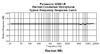
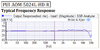
Two 10uF capacitors in series produce 5uF. Then the -3dB cutoff frequency into 5.1k is 6.3Hz.
Every jumper wire is an antenna that picks up interference. All the rows of contacts and long wires on a breadboard are antennas.
The circuit has many RC low frequency cutoffs. Maybe their total cuts heatbeats.
They certainly do, particularly C4, C5, and C8 - but also C9 and C10 (why two?). Healthy heartbeats can be well below 1Hz, particularly in super fit people - and also unhealthy heartbeats could be uncommonly slow as well - mines the opposite, uncommonly fast and variable.
A young friend and workmate was in hospital many years ago, and they wouldn't let him out - so he asked why, to be told his heartbeat was far too slow and they were concerned with it. He pointed out that was perfectly normal, and due to his level of fitness (we called him Arnie, for obvious reasons - even though he was only short).


 . I think I will try the first one as it has wider operating voltage range. Many thanks for your recommendation!!