Electro Tech is an online community (with over 170,000 members) who enjoy talking about and building electronic circuits, projects and gadgets. To participate you need to register. Registration is free. Click here to register now.
Welcome to our site! Electro Tech is an online community (with over 170,000 members) who enjoy talking about and building electronic circuits, projects and gadgets. To participate you need to register. Registration is free. Click here to register now.
If you don't need the galvanic isolation and you want a little more oomph than a capacitor divider, you can use a simple chopper circuit. Where anything above a certain voltage turns OFF a transistor thus not allowing any mains above a certain voltage to flow.
You are right, I seem to have had this reversed/wrong. This could make it easier. Unless I'm mistaken - again - I can get away with something like 15(p):2(s) then. With currents that low, this could be simple. Depending on the core, I will have to go a little higher with the turns (~ 400:6). This still leaves lots of room for imperfection and wiggling.
The number of turns needed on the primary depends on the voltage, frequency and the cross-sectional area of the core. It does not depend on the current or power rating.
The number of turns needed goes in proportion to voltage and down in proportion to the frequency and the area or the core.
If you have too few turns, the core will saturate and there will be no back-emf to reduce the current flow, which could get huge.
A small 50 Hz 230 V transformer may well have as many as 2000 turns on the primary.
If you are experimenting, it's a good idea to put a conventional incandescent lamp in series, so if you get it wrong, the lamp just lights.
Yes, thank you. Or put a capacitor upfront and add a fuse in case they find resonance.
I think I'm going to be lazier than that and simply unwind/or add to the first or second coil on a very small transformer until I reach something above 30V.
I think I'm going to be lazier than that and simply unwind/or add to the first or second coil on a very small transformer until I reach something above 30V.
I was only inquiring about a power supply. I was wondering, if there were any integrated circuits that could help boost efficiency and simplicity - any real alternatives to the "old" (inefficient) transformers or voltage dividers. As an example, for switching currents with high voltages (such as 230V) there are cheap chips, which have it all integrated (optocoupler + TRIAC + ...), available now. They make life so much easier (often only four pins!) and things cheaper. I hope I will never get to see a relay again.
If you told us EXACTLY what you're wanting to do, then we make sensible suggestions. Your suggestion that you want 30V AC makes a huge difference to what you might use, effectively ruling most methods (assuming you mean 50Hz AC).
As for 'inefficient' transformers, they are the most efficient device available - although to be fair, the bigger the better, and small ones aren't as efficient as huge ones.
30V AC at 50-60Hz (little variation doesn't matter), 5-10mA needed. Goal: efficiency (24/7). That is pretty precise.
So far, any transformer I can find is far too big (and therefore likely less efficient than a voltage divider).
I believe people want to understand what you will be using this 30 volts for, which you seem oddly reluctant to say. Why does it matter? Both for life-safety and because the application may provide a direction for the how.
You've blown off every question and comment about the safety issues of capacitive and resistive droppers and shown some confusion (ignorance?) about what fuses will protect against. This with and refusal to say what you plan to do with it make people very reluctant to offer any suggestions.
That's the problem, you're not telling us what you're trying to do, just how you're trying to do it - or even if it's a PSU for something, or just a signal.
As far as you've told us, the only sensible answer is a commercially bought 30V (or 15-0-15) mains transformer.
I wonder, would two 240V to 15V transformers, with both primaries and secondaries in series, be more efficient then a single 240V to 30V transformer? My thinking is reduced flux swing, so reduced hysteresis loss, and lower magnetising current, so reduced I*R losses in the primary.
<EDIT>
It's been pointed out that this makes no sense - what I meant was two 240V to 30V transformers.
If transformer A has more load it will try to pull more load from the power line causing it to have less voltage across its primary.
Two unequal loads in series (across a voltage source) will not divide equally. You likely will have too much voltage on one 15V output and not enough across the other.
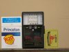
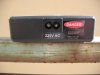
I just happened to have found a very small 2x15 bugger. I attached the measuring device to the outer pins and bridged the middle with pliers - voilà.
Unless I'm mistaken, this will be slightly more efficient than the voltage divider currently in use. Though far from efficient (it doesn't even get warm), let's call it an improvement.
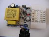
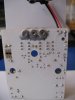
Here is how you work and deal with tranformerless supplies if you understand them:
Specifications:
125mA @ 10.15VDC continious output for ever @ 220VAC
can handle 3 phase input @ 380V AC for 5 mins when things go wrong from your electricity supplier
rugged as they come
tested non stop for 5 years, no sign of failure anywhere
gotta understand what youre doing
This site uses cookies to help personalise content, tailor your experience and to keep you logged in if you register.
By continuing to use this site, you are consenting to our use of cookies.

")