Continue to Site

Welcome to our site!

Electro Tech is an online community (with over 170,000 members) who enjoy talking about and building electronic circuits, projects and gadgets. To participate you need to register. Registration is free. Click here to register now.

  • Welcome to our site! Electro Tech is an online community (with over 170,000 members) who enjoy talking about and building electronic circuits, projects and gadgets. To participate you need to register. Registration is free. Click here to register now.

Edge detection circuitry

Status
Not open for further replies.

raviram87

New Member
hello people...

finally i got outputs on my eye based project for which i wish to thank all members for their help...

at the output of the circuit designed, i get two waveforms as the result... (i apologise for the rather shoddy images)..
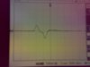
(1) one for moving eyes to right and coming back to centre. (refer image1)
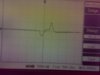
(2) one for moving eyes to LEFT and coming back to centre. (refer image2)

as u can see the 2 waveforms are symmetric....
moving right is assosciated with a RISING edge first, whereas moving left is assosciated with a FALLING edge first...

is there any way by which i can differentiate these movments???
i.e., i need a circuit that can do the following...
(1) if it detects a RISING edge first, then conclude it is a RIGHT movement and produce some result (say a HIGH voltage)...
(2) if it detects a FALLING edge first, then conclude it is a LEFT movement and produce some result (say a LOW voltage)...

need some help on this..... thanks :)
 

Attachments

  • Image1.jpg
    Image1.jpg
    323.6 KB · Views: 250
  • Image2.jpg
    Image2.jpg
    347.8 KB · Views: 205
You could have two comparators wired so that one detects "less than zero" and the other detects "greater than zero" and then only respond when the comparators trigger in the right order within a certain time limit. THis would take two pins and some coding.

You coudl replace the two pins and coding probably by some combination logic which would do the same thing (although I'm not sure how you would detect 3 states with just one output pin- ie. moving left, moving right, nothing detected) so this circuit might need 2 output pins.
 
Last edited:
thanks for the reply...

if u see image1, the output first goes high (as the eyes move right), then falls down (as the eye comes back from right to centre) and reaches a constant level...

if i use a comparator, then i detect greater than 0 first and i do some operation, but as the coltage then falls less than 0, the comparator will do the other opeartion also rite?? i do not want this...

wat i am trying to say is...
(1) voltage above 0 detcted (GOOD! comparator does wat i desire)
(2) voltege then fallss below 0 and then reaches 0 (BAD! comparator might do wat i dont want)

so is there a way by which say the comparator detects "greater then 0" and does something and then even if the voltege goes "less than 0", it does not do anything.... i.e., say switch off comparator once the FIRST edge is detected....

is this possible?
 
That's why you need two comparators to detect both the rise and fall, and use or combination+timer logic to produce the output you want.

A D-flip flop captures a logic value on the rising edge of the clock I believe. I don't have time right now to think about it too much but if you placed an inverter in front of the clock pin of a DFF then it would capture a signal on the falling edge. You can set the "signal to be captured" to be 1 when you are searching for a signal and reset the DFFs after you have found it. You'd need other circuitry to figure out which DFF triggered first to find direction.

Are you realy interested in detecthing the symmetry of the rising/falling edge, and then detecting the falling/rising edge? Or are you fine with just detecting the first rising edge, or the first falling edge- that's much easier and simpler to do.
 
Last edited:
thanks again for ur detailed reply...

as u said.. i am interested in just detecting the first rising or the first falling edge... can u help me with details on that???

thnks... :)
 
I already told you everything I have time to. Sit down and thick about it carefully...using two comparators, one to measure the rising edge, one to measure the falling edge, and some code or extra circuitry to detect the order that the comparators trigger in. The output of the comparator has nothing to do with the output state you want. A comparator only detects the state at instances in time, not over time. Your event occurs over time. So your output circuitry will control the output states you want, not the comparator.
 
Status
Not open for further replies.

Latest threads

New Articles From Microcontroller Tips

Back
Top