Continue to Site

Welcome to our site!

Electro Tech is an online community (with over 170,000 members) who enjoy talking about and building electronic circuits, projects and gadgets. To participate you need to register. Registration is free. Click here to register now.

  • Welcome to our site! Electro Tech is an online community (with over 170,000 members) who enjoy talking about and building electronic circuits, projects and gadgets. To participate you need to register. Registration is free. Click here to register now.

Easy PIC12f683 problem

Status
Not open for further replies.

Scoobystu

New Member
Hello, it will become apparent very quickly that I am a beginner at this whole pic programming thing. I have read the newcomer section and looked at a lot of the weblinks but am still struggling with a delay problem.

I am using the PicKit2 and can get the LED to go off and on using the switch but cannot get it to flash when I try the simple delay program that I plagerised from the internet.

Code:
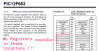
Loop1 decfsz COUNT1,1
goto Loop1
decfsz COUNT2,1
goto Loop1
Code:

I have assigned the COUNT1 equ 08h and COUNT2 equ 09h.

When I run the debugger in mplab and step through the program it never comes out of the first decfsz COUNT1,1 instruction. It just continues to go round.

This is then emulated by the LED when I download the program onto the PIC in that it simply stays on all the time. I have spent a few nights on this trying various things and am really in need of some help.

As I am a complete newcomer to PICs and programming I am unsure if there is anything else I need to set up before starting the decrement instruction.

Do I need to assign a value to the 08h and 09h addresses before the decrement instruction starts?

Or do I need to set the internal timer up in some kind of fashion before hand?

I would really appreciate some help with this.

My main aim is to build a timer circuit that will have about a 2.5 - 3 minute delay. Have one LED lit when the timer is off, then when the timer starts turn the LED off and turn another one on. When the timer (delay) ends sitch the original LED back on and turn the other one off. Simple..... or so you would think.

Cheers

Stu
 
This would answer your question.
 

Attachments

  • empty.png
    empty.png
    30.7 KB · Views: 608
yes that would appear to explain it!! I was under the impression that they were writable as it said unimplemented. Thanks for that.
 
Also, don't forget to shut off the comparator if you are not using it. After not touching the 14-bit cores in nearly a year, I was involved in a very simple project using the 12F683 but I was stuck debugging what should have been a very simple program for nearly 2 days before I noticed that the comparator is turned on by default. I shut it off and everything worked properly.
 
Thanks for pointing that out Phalanx. I will be using the comparator at a later date but I want to crawl before I can walk.

I take it the comparator is switched off and on in the config line, or do I do it via CMCON0?

I am using the MPLABS .asm template. I couldn't figure out how the MCLR switch was working as an input rather than MCLR until I read the top line and it said MCLR_OFF. Bit of a steep learning curve. There is a lot to learn. Hopefully once I get the basics I will be able to figure things out a bit better myself. I fear that may never happen tho....
 
Scoobystu said:
Thanks for pointing that out Phalanx. I will be using the comparator at a later date but I want to crawl before I can walk.

I take it the comparator is switched off and on in the config line, or do I do it via CMCON0?

It's done via a couple of lines of code, it's very clearly explained in the datasheet - even giving you the exact code you need.
 
OK I changed the code to read Count1 equ 20h and Count2 equ 21h but it still doesn't work. Is the comparator a red herring or do I need to sort it out first?

I take it that I really need to set up the CMCON0 register as described in page 33 of the data sheet? Otherwise I will encounter problems?

The other area I noticed was that to switch the comparator off Bits 2 - 0 in CMCON0 should be '111' as described on page 49. CM<2:0>=111.

I suppose that would make sense as the
MOVLW 07h
MOVWF CMCON0
would do that for you!?

Should I just put the whole piece of code into my program? Will this make my DECFSZ instruction work?
 
Scoobystu said:
OK I changed the code to read Count1 equ 20h and Count2 equ 21h but it still doesn't work. Is the comparator a red herring or do I need to sort it out first?

I take it that I really need to set up the CMCON0 register as described in page 33 of the data sheet? Otherwise I will encounter problems?

The other area I noticed was that to switch the comparator off Bits 2 - 0 in CMCON0 should be '111' as described on page 49. CM<2:0>=111.

I suppose that would make sense as the
MOVLW 07h
MOVWF CMCON0
would do that for you!?

Should I just put the whole piece of code into my program? Will this make my DECFSZ instruction work?

If you check my PIC tutorials, most of them use the 16F628 - this needs the comparators disabling as well, so you can see how it's done.

Also, don't write code like this

decfsz COUNT2, 1

Use the MicroChip provided equates, it should read

decfsz COUNT2, F

So it writes back to the GPR and not W (I've no idea which '1' does, because it's not something I would ever do). By using the provided 'names' it makes the code more readable, and there's less chance of errors.
 
OK thanks for your help so far. I think we are nearly there. I now have a flashing LED thanks to your help. I am still unsure how I managed it tho. I had to delete some of your code piece by piece to try and get rid of the following error I was getting when I tried to compile it.

"Error - section 'RESET_VECTOR' can not fit the absolute section. Section 'RESET_VECTOR' start=0x00000000, length=0x00000054
Errors : 1"

The code I used that made it work was simply
Delay_0
decfsz counta, f
goto $+2
decfsz countb, f
goto Delay_0

decfsz count1 ,f

retlw 0x00

If I tried to put values in the GPR then I continually got the above error message, except the length would change now and again as I varied the values.

I can get the LED to flash on and off at different rates by using the call function several times, however I don't have the ability to tailor the delay to 3 mins (and I don't think using the call delay function about 1000 times would be ideal). If you could indicate what you think might be the reason I am getting this error message I would be very grateful.

What does the '$' symbol do?

I think I can see light at the end of the tunnel.....

PS How can I post my full code up here for scrutiny?
 
Scoobystu said:
What does the '$' symbol do?

It's the current address, so 'goto $-2' jumps back two places, it's explained in the MPASM helpfile.

I think I can see light at the end of the tunnel.....

PS How can I post my full code up here for scrutiny?

Use the 'code' button to enclose it, click on 'advanced' to make it appear.
 
OK, in an attempt to stop hassling you I sent a message to the Microchip technical support who usually take a few days to respond. However they responded quite quickly.

What I should have pointed out in the last post is that when I created my project in MPLABS using the wizard I selected the appropriate template and linker files for the 12f683. When I tried to build it however (without any code and in accordance with the tutorial that came with MPLABS software) it constantly gave me an error message. I sent an email to Microchip (about 3 weeks ago) and they reccomended that I change the linker file, see below

am trying to develop some code to create a timer that will switch on a transistor.

I followed the Tutorial in the MPLAB users guide and it worked out as described. When I tried to do the same for a PIC12F683 I got to the point where I had used the project wizard to select the template files and the linker files. When I tried to Build the project I got the following error message.

"MPLINK 3.94, Linker
Copyright (c) 2005 Microchip Technology Inc.
Error - section 'INT_VECTOR' can not fit the absolute section. Section 'INT_VECTOR' start=0x00000004, length=0x00000010
Errors : 1

BUILD FAILED: Mon Jul 31 10:26:34 2006"

As I am completely new to this I need some advice on how to get the linker files to work with my chosen 12F683 chip.

Thanks

Stuart
Resolution: Hello Stuart,

If you edit the linker file such that the Vectors section ends at 0x1F and the start of Page is at 0x20 your code should build without any additional errors. See below,

CODEPAGE NAME=vectors START=0x0 END=0x1F PROTECTED
CODEPAGE NAME=page START=0x20 END=0x7FF

Regards.

After that sure enough the project built without any further errors, until now.

The message I sent today described my current problem with the delay and their suggestion was to revert back to the original linker file!! AAAAAArrrgghhh. Surely if I revert to the original file then the project will not build at all before I even write any code.

I am officially struggling now.
 
Have you considered programming in 'absolute' mode instead of 'relocatable' mode? Just get rid of the linker script in your project and assign your code and variables to absolute addresses.

Relocatable code is great when you start writing gargungous programs spread across several files but it's more trouble than it's worth for small programs (and newcomers).

Here's what 'absolute' code might look like;

Code:
        list p=12F683, b=8, c= 102, n=71, t=on, st=off, f=inhx32
;******************************************************************
;*                                                                *
;*  Filename: 12F683 Example.asm                                  *
;*    Author: Mike McLaren, K8LH    (k8lh@arrl.net)               *
;*      Date: 31-Aug-06  (revised 31-Aug-06)                      *
;*                                                                *
;*   PWM Example                                                  *
;*                                                                *
;* - Uses 12F683 INTOSC (8-MHz)                                   *
;*                                                                *
;*     MPLab: 7.40    (tabs=8)                                    *
;*     MPAsm: 5.03                                                *
;*                                                                *
;******************************************************************

        #include        <p12f683.inc>
        errorlevel      -302    ; disable bank warning messages

        __config        _FCMEN_OFF&_IESO_OFF&_MCLRE_OFF&_WDT_OFF&_INTOSCIO
;
;       _FCMEN_OFF              ;
;       _IESO_OFF               ;
;       _BOD_ON                 ; default
;       _CPD_OFF                ; default
;       _CP_OFF                 ; default
;       _MCLRE_OFF              ; use MCLR pin as an input
;       _PWRTE_OFF              ; default
;       _WDT_OFF                ;
;       _INTOSCIO               ;
;

        Temp    equ     0x20            ; absolute variable assignment

;******************************************************************
;*                                                                *
;*                                                                *
;*                                                                *
;*                                                                *
;*                                                                *
;******************************************************************

        org     0x0000

Vect_Reset
        clrf    STATUS          ; force bank 0                    |B0
;
;  initialize peripherals and port I/O
;
        movlw   b'00000111'     ;                                 |B0
        movwf   CMCON0          ; turn comparator off             |B0
        clrf    GPIO            ; clear GPIO output latches       |B0
        bsf     STATUS,RP0      ; bank 1                          |B1
        clrf    ANSEL           ; turn off analog pin functions   |B1
        clrf    TRISIO          ; set all pins as outputs         |B1
;
;  setup INTOSC for 8-MHz operation
;
        movlw   b'01110001'     ;                                 |B1
        movwf   OSCCON          ; 8-mhz INTOSC system clock       |B1
Stable  btfss   OSCCON,HTS      ; oscillator stable?              |B1
        goto    Stable          ; no, branch, else                |B1
        bcf     STATUS,RP0      ; bank 0                          |B0
;
;  configure PWM for 20-KHz and 50% duty cycle
;
        movlw   b'00000000'     ;   '000000001'                   |B0
                                ;    0-------  unused
                                ;    -0000---  postscaler 1:1
                                ;    -----0--  TMR2 off
                                ;    ------00  prescaler 1:1
        movwf   T2CON           ; 0.5-usec ticks (8-MHz clock)    |B0
        bsf     STATUS,RP0      ; bank 1                          |B1
        movlw   d'100'-1        ; 100 * 0.5-usec ticks            |B1
        movwf   PR2             ; 50.0-usec period (20-KHz)       |B1
        bcf     STATUS,RP0      ; bank 0                          |B0
        movlw   d'50'           ;                                 |B0
        movwf   CCPR1L          ; set PWM duty cycle 50%          |B0
        movlw   b'00001100'     ;   '00001100'                    |B0
                                ;    00------  unused
                                ;    --00----  DC1B1:DC1B0
                                ;    ----1100  PWM mode
        movwf   CCP1CON         ; turn on PWM mode                |B0
        clrf    TMR2            ;                                 |B0
        bsf     T2CON,TMR2ON    ; start TMR2                      |B0
;
Loop    goto    Loop            ; loop indefinately               |B0
;
        end
 
Nigel Goodwin said:
You might do what I do?, use MPASMWIN and not MPLAB, no linker files, and no messing about!.
That may have been a viable recommendation in the dark ages, but there are far more advantages to using MPLAB now days than there are disadvantages.
 
Originally Posted by Nigel Goodwin
You might do what I do?, use MPASMWIN and not MPLAB, no linker files, and no messing about!.

You can use MPLAB as your IDE without having to to mess about or use the Linker etc, just use the 'Quickbuild' option from the Project drop down menu.
 
Alright dudes I don't want to start an argument here.

As a newcomer to this kind of thing I blindly followed the tutorial that comes with MPLABs. As you say it might be better for massive projects but for the stuff I am trying to do it might not be necessary. I read about linker scripts and the technospeak that is in the manual didn't really help.

I wasn't aware that I could program in absolute mode rather than relocatable mode as I thought that the way I am doing it was the only way to do it ( I am not confident enough yet to try different things). I suppose it is much like relying on software to take care of stuff that is usually pretty standard - but not everyone can use the standard software and if you don't know that you might not need it then you are stuck. I'm sure that makes sense to someone.

So, Mike, basically I could remove the linker script from the project and enter code similar to what you have posted and build the project sucesfully?

Don't want to sound completely daft but whereabouts would I insert my code?

So, Nigel, I could use MPASMWIN. I never looked at that, Is it the predecessor to MPLABS?

It seems that at every point I run into a problem the options just seem to increase exponentially!!

One day I dream of achieving something that was achieved about 40 years ago!!
 
Funny, most of the code examples you'll come across on the internet and on PICLIST will be 'absolute' code. Have you looked at and studied any example code out there?

While I applaud you for diving right in, it seems you're missing some of "the basics". May I recommend you supplement your "hands-on" programming with a good tutorial at the Elmer 160 home page? It covers the basics all the way up to 'relocatable' code and it helps reinforce proper programming practices and style (where other tutorials fall short).

Mike
 
Scoobystu said:
So, Nigel, I could use MPASMWIN. I never looked at that, Is it the predecessor to MPLABS?

MPASMWIN is installed along with MPLAB (which is the only way to get it), and it's a plain assembler - presumably the assembler that MPLAB actually calls?. Just run it, open a .ASM file in the file requester, and click 'assemble', job done - a nice .HEX file to load.

I've always found MPLAB rather over-bloated and complicated to use, so have never bothered doing so - but I come from the DOS only days of PIC's, long before MPLAB was thought off!.

I seem to recall the MPASM is also installed along with MPLAB (or at least it was on older versions?), that's a DOS assembler.
 
Thanks to everyone taking time to post on here.

Anyway, yes I agree I do need to get a basic understanding, although I thought that I was starting at a basic level!! It would appear not. I prefer to start at a basic level so that I can sort out problems such as this when I run into them.

I have looked at a lot of websites about PIC programming but some are more easily read than others. Unless you know what you are looking for it is hard to determine what is important and what isn't. Or what applies to your situation and what doesn't. When I get my delay loop to work my next project is a website showing people how to write and execute simple programmes!!

The one feature I liked about MPLABS is that it has a simulator that would show you your program working step by step. Although it doesn't show me what I want to see so it is pretty pointless really. I take it MPASMWIN would tell you if your code did not build before you downloaded it to the PIC.

All these questions and more... I think I will have to go back and look at an alternative (read simpler) way of assembling my code. Why can't I think like a computer?? I will look at the Elmer 160 tutorials and will return when I have completed them!
 
Scoobystu said:
The one feature I liked about MPLABS is that it has a simulator that would show you your program working step by step. Although it doesn't show me what I want to see so it is pretty pointless really.

Personally I've never used the simulator, and never felt the need - there was a DOS based one, and that was truely horrible!.

I take it MPASMWIN would tell you if your code did not build before you downloaded it to the PIC.

Yes, it gives you error messages, and won't create the .HEX file if it fails. Any errors are written to a .ERR file.
 
Status
Not open for further replies.

Latest threads

New Articles From Microcontroller Tips

Back
Top