Continue to Site

Welcome to our site!

Electro Tech is an online community (with over 170,000 members) who enjoy talking about and building electronic circuits, projects and gadgets. To participate you need to register. Registration is free. Click here to register now.

  • Welcome to our site! Electro Tech is an online community (with over 170,000 members) who enjoy talking about and building electronic circuits, projects and gadgets. To participate you need to register. Registration is free. Click here to register now.

Early or Late Christmas present

Status
Not open for further replies.

MrDEB

Well-Known Member
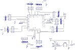
Well here are the Diptrace gerber files if you want to make for 2022 Christmas.
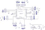
Small enough for a tree ornament.
I made several but using 1206 LEDs (too bright) so this one usines 805 LEDs.
All the middle LEDs (13) are white while all the outer LEDS are blue but use your own judgement.
Plan is to gradually dim the white LEDs then gradually go bright.
The resistor arrays are 150 ohms.
 

Attachments

  • star 2022 board_gerber.zip
    68.9 KB · Views: 230
  • Like
Reactions: 3v0
am not used to diptrace and therefore I might find so much problem with this project. Csn you please share the KICAD gerber files so that i can be able to work with KICAD and give you the feed back. Also if you have a valentine present you can share too. Thanks!
 
here is the schematic. Suggest using 330 resistorarrays in 1206 pattern.
Sorry I don't do KIDCAD. If you order boards using the gerber files I posted you should be fine.the leds are 1206 package as well'
 

Attachments

  • star 2022.jpg
    star 2022.jpg
    380.1 KB · Views: 224
I have no idea what software you're using to create schematics, but you seem to have different names for the same net????

For example, the "5V+" net appears to also be labeled NetPort6, NetPort1, NetPort42 and NetPort62.
Same thing with the GND net. How in the world do you verify that things are connected correctly?

Doesn't your software complain about the same net having different names? If not, you need to trash it and get something better.

The connection to MCLR/R5 looks to be incorrect, but who could follow that mess?
 
I posted the wrong file here is my latest file using 0805 leds
I had a harddrive issue and still trying to get files for diptrace correct folder. I have tooo many files that are same but minor changes.
 

Attachments

  • star 2022-1.jpg
    star 2022-1.jpg
    361.1 KB · Views: 213
Well, that's a little better.

So your nodes labeled "+5V" and "5V+" are the same?
Maybe "+5V" is some sort of single pin part/test point or something?
 
they are bacally Vcc. In the schematic they both highlite at same time.
Your new nick name is EAGLE EYE
 
I am trying out my new hot air rework gun to solder on the 35-0805 leds on one of my stars.
Used a stencil and it worked ok but some pads didn't get enogh solder paste.
THINKING of a simple method to test all the leds. Have yet to solder the pic on the board but wondering if I applied 5 volts to all 35 pins of the pic/ Think of itas a hot continuity tester. Isoate the grd and vcc pins (#6,, 7, 29, 28) then using a flat copper square to apply power to the pins. When an led lights its a good connection. Do this whild soldering the leds on.I had a few that I got backwards.
Have done similar but with the pic soldered then cycle through the ports.
Supposely tomorrow the 330 ohm tresistor arrays will arrive from Newark Electronics.
 
After thinking about the issue of turning on all the LEDs while assembling it struck me!
Solder a thin wire across all the resistor arrays on the pic port side then connect to 5 volts.
This is without the pic installed.
 
finally got the new Christmas PCboard done hopefully.
I need to recheck but no DRC errors etc.
hopefully I uploaded correct format
 
Status
Not open for further replies.

Latest threads

Back
Top