Electro Tech is an online community (with over 170,000 members) who enjoy talking about and building electronic circuits, projects and gadgets. To participate you need to register. Registration is free. Click here to register now.
Welcome to our site! Electro Tech is an online community (with over 170,000 members) who enjoy talking about and building electronic circuits, projects and gadgets. To participate you need to register. Registration is free. Click here to register now.
I had Goggled for Eagle max area and when I saw measurements I tried to respond quickly with the results without reading the details. So going quick is not good in anything!
As for autoroute, this had never worked for me in the past but after your post I did more tests and I realized it was because my PCBs all have some SMD. I tried with only TH and it's all good.
will look at it
Thanks
I need to add a zener maybe as the new PIR needs either 3.3vdc or 8-24vdc
If I use 9 volt batteries then I don't need the zener.
got the idea this morning about adding a solar battery charger which should be fairly easy to add hopefully. I want this unit to be as user friendly as possible.
Also need to decide if I need the pot as the new PIRs have a Cds cell already. Waiting for 3 PIRs on order to try out.
At present will use pcboard / schematic as I have 5 PIRs on hand (older style)
it won't exactly tell me its a 3x2.10 board assuming its inches?
The edited board needs a little more work as it has some 90 degree bends.
Also I need to add two holes to mount the board (found MARK but need to see if it gives coordinates to cone side with the enclosure data sheet.
Add to all this I need some small nuts and bolts, order some 2.1mm power jacks and ac adapters.
Oh yea get hold of the people over at PCB Order | DorkbotPDX to get some boards ordered. I registered but still can't get in the website.
LOTS of little items to do.
If you want to work in Inches select inches as indicated bellow.
Then to get/make the dimension you want, right-click on the line and view/change the values. This is hard to explain but hopefully this can be of some help:
Note that to get the properties I right-clicked on the top line which goes from 0 to 2.55 in on the X axis and obviously 2.85 to 2.85 in on the Y axis as it is horizontal.
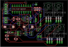
The mounting holes for transistors Q3 & Q4 are nearly intersected with traces. Probably should move the traces at least 1/8" (0.125") away from the holes for fastener clearance.
Also, if transistors Q1-Q4 will be switching large amounts of current (considering they're power types) the traces which are connected to the collectors and emitters should be fattened up considerably.
Q1-Q4 are mosfets that have very little current. Thinking about going with smd instead of TO220
Looking over board I see several minor error, The PIR did not have a connection for power (bottom pin)
will use the suggested post for determine board size.
moved several traces and hopefully got rid of all the 90's
It is not a common thing to find differences between the board and the schematic as long as the schematic is error free.
From within the schematic window you should always click on the ERC tool to make sure you don't have unconnected pins and to approve those errors that are expected. Using components from the library often leads to selecting a part that was poorly designed which makes it hard for wires to connect to its pins, I think this might be the biggest issue which you will find out by validating with ERC. it is at the bottom of the toolset or you can select it from the tool menu at the top.
moved traces around the TO220 mounting holes, added trace to PIR.
Tried deleting the vector font box at bottom of board.
As for mounting holes, need to locate my decimal chart for #4 screws. Plan is to bridge between enclosure mounting stands with plastic strip then screw the pcboard to strip. This will save on board size.
Still contemplating a solar battery charger so 3 AAA batteries can be enclosed inside enclosure and user does not need to change batteries every few months.
NOTE the mosfet amp is not used in battery usage modeso batteries should last awhile.
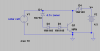
any thoughts on a simple solar battery charger? for 4.5 volts
Thinking of adding the solar battery charger and having the Mosfet (Q1-Q4) stand upright to save board space. height is not a real factor.
weather this would do the deed? is another question. LT Spice looks like it will work.
If you select one of the options just to the right of the layer when drawing a line, it will limit the line to 90 and 45 degrees instead of those interesting angles you have.
Funny. It sounds like the made up the name and then decided to make it into an acronym.
Well, other than CadSoft nobody in their right mind would consider it easy for beginners. Though I didn't have much problem stepping through the tutorials, I think it helps if it's the first thing you learn. People tend to get used to the first thing the learn and complain that everything else does it wrong. I learned Altium and it was a pain. I just had to remind myself that it was just different.
Anyway, sorry I haven't been much help, I've been real busy these last few days and I'll be out of it for the next few as well.
You probably have changed grid size in the schematic inadvertently to odd numbers, e.g. from 0.1inch to 0.045inches (instead of 0.05) and nets do not connect with the same name between pins they should connect. Run an ERC (Electrical Rule Check) and see what it comes up with.
If it shows no errors use the eye-symbol and highlight each net. Make sure the nets connect to the proper pins which should also appear highlighted.
BTW, you might disable top and bottom layer, group the entire board layout and smash all components (smash group).
Then you might move names and values to a position which makes them clearly readable. A smashed part will have reference markings (origins) not only on the part itself, but also at the name and value.
If the letter size is too large you might change it proceeding as before. This time change size group.
To get of 90degree bends move the shorter part of the trace into the angle and "split" it.
Here is my latest design. Added a solar charging section (D3,D4 etc.
Looks wrong but this board is multi-functional.
option with amp (mosfets) or if battery powered then with out amp
If battery powered then vehicle power input mounted on case is not used.
If solar powered battery charger then charger parts are soldered to board as is the amp section if used.
Can not use solar section with vehicle power.
Thinking of turning the mosfets 90 degrees to cut down on pc board real estate.
at present board is 3x2.5inches I think?
The schematic shows the mosfets as 3 pin plugs as the mosafets are standing up.
I need to recheck the board as I used ERC but not sure if all is correct?
This site uses cookies to help personalise content, tailor your experience and to keep you logged in if you register.
By continuing to use this site, you are consenting to our use of cookies.

 , i making it too be more complex