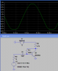
Hi, I've been playing around with the microphone input on my Creative SoundBlaster Live 24-bit card and a low impedence, unbalanced dynamic microphone designed for a radio tranciever. The input level is extremely low, and in my readings I have found that cheap condenser mics require bias voltage, and put out a much larger voltage signal. I also found that this particular soundcard outputs +5V for bias on a separate line from the input of the speaker, using all three pins of a standard stereo jack. I found one person who cleverly designed the circuit below to use the bias voltage to power a simple Class A amplifier to boost the signal of a dynamic mic to something the sound card will pick up:
**broken link removed**
(Picture Source)
I'm trying to understand exactly how this amp works, and I'm trying to learn the concept of impedance matching. I'm also trying to build and use this circuit in practical application.
My first problem is that the BC547B isn't readily available at the RadioShack down the street. Rather than order it, I'd like to substitute it and learn more about the parameters that govern transistor selection. Here's the **broken link removed**, as well as the substitute I selected: the 2N4401. This substitution yielded a circuit that doesn't really provide sufficient gain. I'm guessing by looking at the datasheets that the 2N4401 was designed to function at higher currents and doesn't have a high enough hFE at low base current.
Other possible substitutions are the 2N3903, and the 2N2222. I'm guessing by the spec that the 2N222 would be the best choice as it is designed to work at roughly the same currents as the BC546, correct?
For the sake of completeness, here is the data sheet for the MPS2222A, which is Radio Shack's equivelent to the BC546, but not available to me currently.
My next question is in relation to how this circuit works. My understanding is that the signal first enters R1. R1 is present because the base impedance of the transistor is low. R1 increases the impedance presented to the mic and prevents it from being loaded down. C1 prevents any DC current from passing back to the microphone. R2 is the bias resistor which adds voltage to the incoming signal so that the signal is no longer alternating but always above ground voltage. This is characteristic of a Class A amp. I don't understand how to calculate the proper amount of bias here, and I read that this affects the amount of amplification. I'm guessing that with my higher power 2N4401, I would have to decrease the value of R2 to increase bias voltage to get higher gain out of the transistor, but this would also waste current from the +5V source. As for the output, C2 prevents DC from flowing out the output. Since this is electrolytic, though, I would think that it would be reverse biased during the negative part of the audio wave and not work correctly. Wouldn't this be better as a thin film cap? C3 is just a filter to provide cleaner voltage from Vin, and R3 is to knock down the voltage to the appropriate level to power the transistor. I'm not sure how the value for R3 is chosen, either. Using ohm's law, if the transistor is putting up no resistance, 1mA is flowing through R3. So, I'm guessing that 1mA is desired on the emitter, so the R3 value was chosen accordingly. Would this need to be modified for use with the 2N4401?
Finally, how would you determine the output impedance? I'm guessing that this would be a characteristic of the transistor. I know that the soundcard input is high impedance. My understanding is that a low impedance output into a high impedance input offers optimum voltage transfer, however high-impedance in and out offers optimum current transfer. Which provides more gain to the soundcard? I read that with modern equipment, low-Z into a high-Z input is normal and desireable.
Thank you very much for any input!!!
TJ Harrell
**broken link removed**
(Picture Source)
I'm trying to understand exactly how this amp works, and I'm trying to learn the concept of impedance matching. I'm also trying to build and use this circuit in practical application.
My first problem is that the BC547B isn't readily available at the RadioShack down the street. Rather than order it, I'd like to substitute it and learn more about the parameters that govern transistor selection. Here's the **broken link removed**, as well as the substitute I selected: the 2N4401. This substitution yielded a circuit that doesn't really provide sufficient gain. I'm guessing by looking at the datasheets that the 2N4401 was designed to function at higher currents and doesn't have a high enough hFE at low base current.
Other possible substitutions are the 2N3903, and the 2N2222. I'm guessing by the spec that the 2N222 would be the best choice as it is designed to work at roughly the same currents as the BC546, correct?
For the sake of completeness, here is the data sheet for the MPS2222A, which is Radio Shack's equivelent to the BC546, but not available to me currently.
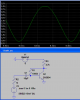
My next question is in relation to how this circuit works. My understanding is that the signal first enters R1. R1 is present because the base impedance of the transistor is low. R1 increases the impedance presented to the mic and prevents it from being loaded down. C1 prevents any DC current from passing back to the microphone. R2 is the bias resistor which adds voltage to the incoming signal so that the signal is no longer alternating but always above ground voltage. This is characteristic of a Class A amp. I don't understand how to calculate the proper amount of bias here, and I read that this affects the amount of amplification. I'm guessing that with my higher power 2N4401, I would have to decrease the value of R2 to increase bias voltage to get higher gain out of the transistor, but this would also waste current from the +5V source. As for the output, C2 prevents DC from flowing out the output. Since this is electrolytic, though, I would think that it would be reverse biased during the negative part of the audio wave and not work correctly. Wouldn't this be better as a thin film cap? C3 is just a filter to provide cleaner voltage from Vin, and R3 is to knock down the voltage to the appropriate level to power the transistor. I'm not sure how the value for R3 is chosen, either. Using ohm's law, if the transistor is putting up no resistance, 1mA is flowing through R3. So, I'm guessing that 1mA is desired on the emitter, so the R3 value was chosen accordingly. Would this need to be modified for use with the 2N4401?
Finally, how would you determine the output impedance? I'm guessing that this would be a characteristic of the transistor. I know that the soundcard input is high impedance. My understanding is that a low impedance output into a high impedance input offers optimum voltage transfer, however high-impedance in and out offers optimum current transfer. Which provides more gain to the soundcard? I read that with modern equipment, low-Z into a high-Z input is normal and desireable.
Thank you very much for any input!!!
TJ Harrell
Last edited: