Continue to Site

Welcome to our site!

Electro Tech is an online community (with over 170,000 members) who enjoy talking about and building electronic circuits, projects and gadgets. To participate you need to register. Registration is free. Click here to register now.

  • Welcome to our site! Electro Tech is an online community (with over 170,000 members) who enjoy talking about and building electronic circuits, projects and gadgets. To participate you need to register. Registration is free. Click here to register now.

Dumb question: translating a voltage

Status
Not open for further replies.
Since the LED current is very low and can be driven from the output of the opamp then remove the transistor.

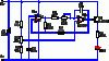
I don't see the point of converting the original fading and brightening LEDs circuit into this circuit where the LEDs simply turn off then flash on. The triangle waveform is not used anymore when the capacitor is blinking the LEDs.
 
The complete circuit (the LED throbber) is attached below, plus my modifications, shown above. (Simple op-amp triangle-wave generator.)
 

Attachments

  • led_throb1_sch.gif
    led_throb1_sch.gif
    9.6 KB · Views: 321
According to my simulations, increasing the value of R3 will increase the amplitude of the output. You might try going from 39k to 60-80k and see what happens.

Edit: If you want to experiment with circuits it's a lot easier to simulate them before you build them to understand and optimize their design. LTspice form Linear Technology is free and works well.
 
Last edited:
According to my simulations, increasing the value of R3 will increase the amplitude of the output. You might try going from 39k to 60-80k and see what happens.

I did that, and it made a remarkable difference. Much higher voltage swing. Now the LEDs light fairly brightly from a 9-volt supply. Thanks!

Certainly a common-emitter stage driving the emitter follower should help if you bias it properly. Without seeing your circuit I can't help you there.

So now that you've seen the circuit, do you think you might toss me a suggestion or two? Maybe not give me every last little detail--after all, I am trying to learn something here--but I'd really appreciate you taking a stab at a possible improved amp stage or two.
 
I'd really appreciate it if someone would be so kind as to post at least a suggestion of a circuit to boost the output to my LEDs here, say enough to drive up to a few (3-6) medium-intensity ones, not high-intensity power-suckers.

I'd like to see what a common-emitter stage plus an emitter follower would look like.

I'm also wondering where the "translation" circuit (RC) should go: should it go at the input as shown here, or between two stages? In other words, is it better to translate the voltage first, then amplify it, or amplify and then translate?

I do have LTspice and have fooled around with it a little bit, but I'm still fairly far down on the learning curve. I might try this as a first project. Anyone know of any good LTspice forums?
 
I'd really appreciate it if someone would be so kind as to post at least a suggestion of a circuit to boost the output to my LEDs here, say enough to drive up to a few (3-6) medium-intensity ones, not high-intensity power-suckers.
I think you are limited in the number of leds you can drive because you are using a 9 volt battery.
I'd like to see what a common-emitter stage plus an emitter follower would look like.
I think you have accomplished the same result by increasing the value of R3, and also with fewer parts.
I'm also wondering where the "translation" circuit (RC) should go: should it go at the input as shown here, or between two stages? In other words, is it better to translate the voltage first, then amplify it, or amplify and then translate?
Im not sure what you mean, to me it looks like the RC is on the output in your circuit ??? This is kind of a brute force method. I would say translate first then amplify but that takes more parts. The other way (like you are using) is fewer parts but big capacitors.
Just my take on it.
Edit: Sorry I dont have any way to post schematics.
 
Last edited:
Help!

So I cobbled this together:

**broken link removed**

It works--sort of. It only lights one LED, so I ASS-U-ME that I'm getting the waveforms indicated above. (I'm sure about the second one, the one that's both positive and negative, because both LEDs light alternately.) So obviously, something's wrong. My nice symmetrical signal (from the emitter of Q1) is getting polarized, the opposite of what I want. What I want to do is to light both LEDs equally and brightly.

I'm sure my biasing is totally wrong, which may account for part (all?) of the problem.

Any help would be appreciated. To reiterate, this is not a matter of coming up with the optimum circuit here. This is a learning exercise for me, and hopefully for any other poor souls who might come this way with questions about biasing and other great existential matters.

Ideally, I'd be able to do this with one transistor. I just tried this to see what would happen.
 
Your second transistor has no base bias. It will only conduct on the rising pulse. You won't get both LED's to work that way anyway. If you want to see both flash, connect one between VCC and the collector of the 2nd bjt, with a series resistor of course. That way one will illuminate when the transistor is on, and the other will illuminate with the transistor is off. There is no other way to get both to flash in the way they are connected.
 
The original circuit does not use an output coupling capacitor so its LED brightens slowly and dims slowly by a variable DC voltage (the triangle waveform).
Your output capacitor feeds AC to the output transistor but it doesn't work with AC because when its base goes less than 0.6V or goes negative then it cuts off, it needs a variable DC input voltage.

If you bias the opamps properly then you can get the NPN transistor to brighten an LED at the same time that a PNP transistor dims another LED and they alternate.
 
Your second transistor has no base bias. It will only conduct on the rising pulse. You won't get both LED's to work that way anyway. If you want to see both flash, connect one between VCC and the collector of the 2nd bjt, with a series resistor of course. That way one will illuminate when the transistor is on, and the other will illuminate with the transistor is off. There is no other way to get both to flash in the way they are connected.

Except that the setup I described in this posting works. Can you explain how or why this works? I can assure you it does: when set to a low frequency, one LED pulses on, goes out, then the other one pulses on. So I ASS-U-ME I'm getting something close to that symmetrical waveform I showed above.

Since it's certainly possible for an amplifier (a properly-biased one, at any rate) to reproduce an AC waveform, I'd like to know how I could do that here. Again, for the sake of learning, not because this is the best way to accomplish this simple task.
 
Last edited:
Except that the setup I described in this posting works. Can you explain how or why this works?
The emitter-follower transistor linearly pulls its output voltage up with the triangle input waveform.
But only one of the 1k resistors pulls the output voltage down so the voltage to the LED is not symmetrical. The circuit needs a push-pull output pair of transistors to do what you want.

Guess what? The output of a 555 is push-pull and will do what you want without a transistor. The max output of an ordinary 555 is 200mA but the Cmos 555 output current is much less.


I can assure you it does: when set to a low frequency, one LED pulses on, goes out, then the other one pulses on. So I ASS-U-ME I'm getting something close to that symmetrical waveform I showed above.

Since it's certainly possible for an amplifier (a properly-biased one, at any rate) to reproduce an AC waveform, I'd like to know how I could do that here. Again, for the sake of learning, not because this is the best way to accomplish this simple task.[/QUOTE]
 
Except that the setup I described in this posting works. Can you explain how or why this works? I can assure you it does: when set to a low frequency, one LED pulses on, goes out, then the other one pulses on. So I ASS-U-ME I'm getting something close to that symmetrical waveform I showed above.

Because the output was capacitively coupled, the current was truly AC. In the last case, using a capacitor between the two transistors doesn't make the output AC, instead it's a pulsed DC.

Since it's certainly possible for an amplifier (a properly-biased one, at any rate) to reproduce an AC waveform, I'd like to know how I could do that here. Again, for the sake of learning, not because this is the best way to accomplish this simple task.

It's possible if the output is capacitively coupled, or a push-pull topography is used with split supplies. Otherwise, the output rides in a DC level.
 
Since it's certainly possible for an amplifier (a properly-biased one, at any rate) to reproduce an AC waveform, I'd like to know how I could do that here. Again, for the sake of learning, not because this is the best way to accomplish this simple task.
Because the output was capacitively coupled, the current was truly AC. In the last case, using a capacitor between the two transistors doesn't make the output AC, instead it's a pulsed DC.

It's possible if the output is capacitively coupled, or a push-pull topography is used with split supplies. Otherwise, the output rides in a DC level.

So I was getting my "AC" (= symmetrical waveform) because of capacitive coupling, correct?. What if I capacitively couple my output stage--wouldn't that remove the DC offset and restore my "AC"? (So far as I can tell, it really is AC: if both LEDs are lighting, I have positive and negative pulses, which looks, smells and tastes like AC to me.)

I could use push-pull, sure, but that would be way overkill, even for the sake of learning ...
 
What if I capacitively couple my output stage--wouldn't that remove the DC offset and restore my "AC"?

Yes. Defnitely. For sure. Had to write enough to make the minumun characters.
 
Here is a site with a pretty good explanation on how to bias.

**broken link removed**
 
Carbonzit, I agree with ronv that you should study transistor biasing so you can better understand what you are doing, rather than semi-randomly trying circuit changes and then us trying to explain why it doesn't work. I also would suggest further study on how capacitors couple AC signals and block dc.

And as I suggested, if you want to learn by modifying circuits to see what happens, you should try using LTspice. It makes it easy to change a circuit and see what is happening at all the nodes, as if you had an ideal oscilloscope to observe everything. LTspice takes a little effort to learn but there are forums that will help you with that, and it's well worth it if you are really interested in learning about circuits.
 
Any way to do it with a single supply?
The original circuit uses a single supply and it slowly fades and brightens its LEDs perfectly.
Adding a coupling capacitor causes the LEDs to simply blink on and off.
There is no need for a dual-polarity supply.
 
Status
Not open for further replies.

New Articles From Microcontroller Tips

Back
Top