Hi guys,
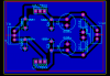
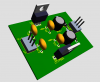
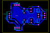
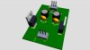
I have designed a PCB for a dual power supply based on both 78xx and 79xx regulator chips.
Plz put your ideas about the layout and the PCB itself (specially the ground plane).
I hope there is not ground loop in y design too.
The input voltage comes from a center taped transformer, the said transformer has two 2200uF caps and two 104 caps to smooth the voltage, thats why I did not use any cap at the input of the below pic.
Furthermore Should I use C1 and C2 in the below pic plz? A guy told me that I should not use them because they cause the regulators to be shorted at the beginning of the start point. What Is your idea plz?
The below regulator will drive a pre-amp based up on Tl074 and the said pre-amp maybe turned on for 24 hours per day.
Thanks a bunch
Attachments
Last edited: