Continue to Site

Welcome to our site!

Electro Tech is an online community (with over 170,000 members) who enjoy talking about and building electronic circuits, projects and gadgets. To participate you need to register. Registration is free. Click here to register now.

  • Welcome to our site! Electro Tech is an online community (with over 170,000 members) who enjoy talking about and building electronic circuits, projects and gadgets. To participate you need to register. Registration is free. Click here to register now.

dual power supply

Status
Not open for further replies.

nabeelkhan634

New Member
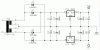
I am using center tapped transformer for making dual power supply ,transformer is of 24-0-24 2 amp . but the problem is that m not getting supply of +24 and -24 instead m getting +12 n -12 volt

Any idea???????:confused::confused::confused:
 
I you post a schematic we can help you better.
 
I guess you used bridge rectifiers both outer taps to the center tap.

You must use two-way rectification to gain ±24V.

Here is the schematic, using linear voltage regulators. The inputs are connected to 24V rectified positive and negative rails.

The center tap is used for common ground.

Boncuk
 

Attachments

  • DUAL-PWR.gif
    DUAL-PWR.gif
    15.6 KB · Views: 1,275
Schematic is the standard circuit used for Leeds & Northrup for instrumentation.

You may need more varied capacitors to catch spikes, depending on the application. This is just the basic filtered circuit.
 

Attachments

  • LnNPowerSupply.jpg
    LnNPowerSupply.jpg
    17 KB · Views: 634
yes my circuit includes bridge rectifier ..Im using the same schematic buddy... and using LM317 and LM337 for positive and negative regulator... and i have 24-0-24 volt transformer but why it is giving +12 -12 volt output. or this circuit gives half input 24 to 12 volt...
 
The unregulated voltages at the inputs of the regulators should be +33V and -33V.
The 2k resistors on the regulators are supposed to be 120 ohms or less. Then when the 5k pots are set at max resistance the outputs of the regulators will try to go to 53.3V but then the regulators will not regulate.

If the resistor is 100 ohms and the pot is 2k ohms then the max output will be 26.25V.
 
Thanks sir, can I ask you something. that how do you know that it is +33v at input?,yes it was near 33. and please tell me , why it won't regulate at 53.3V ....

:- )
 
Thanks sir, can I ask you something. that how do you know that it is +33v at input?,yes it was near 33. and please tell me , why it won't regulate at 53.3V ....

:- )

24 *sqr2 ~ 33.

The LM317 can regulate up to 40V (max.) difference between input and output.

Of course the input voltage must be higher than the output voltage.

To get to 53.3V out of 24V (33) you need a step up converter. Also at 53.3 you can't get the chip to regulate to 12V, since the input to output difference exceeds the maximum allowable value of 40.

Boncuk
 
Last edited:
Thanks sir, can I ask you something. that how do you know that it is +33v at input?,yes it was near 33. and please tell me , why it won't regulate at 53.3V ....

:- )

If you tried to get any kind of voltage out of the 337 or 317 with an input of 53V it is very possible that you have destroyed the part from thermal overload or voltage over load. Trust me, I know from experience. If you want to see their data sheets then I've provided the link to them below.
 

Attachments

  • lm317.pdf
    339.2 KB · Views: 193
  • lm337.pdf
    221.1 KB · Views: 242
Status
Not open for further replies.

Latest threads

New Articles From Microcontroller Tips

Back
Top