Continue to Site

Welcome to our site!

Electro Tech is an online community (with over 170,000 members) who enjoy talking about and building electronic circuits, projects and gadgets. To participate you need to register. Registration is free. Click here to register now.

  • Welcome to our site! Electro Tech is an online community (with over 170,000 members) who enjoy talking about and building electronic circuits, projects and gadgets. To participate you need to register. Registration is free. Click here to register now.

Dual power source LED

Status
Not open for further replies.

IainC

New Member
I want to run an LED such that it illuminates off a constant 12V supply unless a PWM supply (0-100%, 220Hz) is available. Power consumption is an issue when operating off the 12V supply, I'm trying to achieve this through use of analog components only.

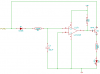
So far I've put together an integrator circuit to turn on a transistor (via a comparator) that feeds the PWM to an LED when the PWM input is present (see below). What I can't work out is how to get the switch-over to 12V when the PWM is absent though! Any ideas please?

Is it as simple as adding in a PNP such that it's turned off if the comparator is detecting a non-zero input?
 

Attachments

  • ScreenShot233.png
    ScreenShot233.png
    13.4 KB · Views: 217
Just an idea: Use a 2nd transistor that is in parallel with the one already in your circtuit. Bias it so that it's normally off when the PWM signal is present ( Capacitor & diode oriented so that the voltage on the capacitor is negative ) When the PWM signal is stopped, then the negative bias is leaked from the capacitor through a resistor. Then, your 2nd transistor truns on. Also, move the LED & series resistor to the collector side of the transistor(s)

-OR-

A better idea would be to replace everything in the drawing ( except the transistor ) with a 555 "Missing Pulse Detector" Don't have a schematic; try google.
 

Attachments

  • LED_PWM.JPG
    LED_PWM.JPG
    89.1 KB · Views: 289
Last edited:
Thanks BrownOut - your reply has made me realise that I left out part of the definition of the problem!

At the system level, the PWM signal is provided by an N-channel MOSFET and goes to other (LED-based) illumination devices that can't light up when the PWM is off, (so the line is either floating, or 12V). I've now included this information in the sketch below - sorry for the previous omission.

The PWM source is fixed - as I'm trying to make an add-on to an existing system for a project I'm working on.
 

Attachments

  • ScreenShot235.png
    ScreenShot235.png
    30.9 KB · Views: 185
Last edited:
What is the peak voltage of the PWM signal?
 
12V relative to the "ground" in the rest of the system.

How about a solution using only passive components? Note the current through the LED as a function of the PWM being there or not.
 

Attachments

  • LedSw.gif
    LedSw.gif
    58.9 KB · Views: 178
Message Removed.

I posted a working model of my orignial idea, then realized I mis-interpreted the problem.
 
Last edited:
Message Removed.

I posted a working model of my orignial idea, then realized I mis-interpreted the problem.

I design the right circuit for the wrong application all the time...:eek:
 
Status
Not open for further replies.

New Articles From Microcontroller Tips

Back
Top