Continue to Site

Welcome to our site!

Electro Tech is an online community (with over 170,000 members) who enjoy talking about and building electronic circuits, projects and gadgets. To participate you need to register. Registration is free. Click here to register now.

  • Welcome to our site! Electro Tech is an online community (with over 170,000 members) who enjoy talking about and building electronic circuits, projects and gadgets. To participate you need to register. Registration is free. Click here to register now.

Dual Isolated Input to Microcontroller

Status
Not open for further replies.

jamesh77

New Member
Hi guys,

Firstly to summaries what i am about to say below, i basically want to mimic the signal that the pic receives from the potentiometer. I however want to leave this old circuit in there so the system can be controlled be input method A or input method B. The reason for doing this, is because i can't change the software on the PIC to use my input method B.

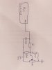
I have attached two images, "image1" is the circuit diagram of an the original circuit, which just provides the PIC with a input from a potentiometer.

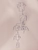
I also want to be able to choose between two input signal's to the PIC, my initial thoughts are provided in image2 which uses a DPDT switch to change between the two input methods. The second control method comprises of another MCU which has its own input signal, which then varies a digital pot proportionally to the input signal.

The problems that i face however is that the PIC and the second MCU must be isolated from each-other, as the PIC is attached to a larger system, and due to the fact they have different supply sources. I therefore need ideas of isolating the two systems and mimicing the signals.

Does anyone have any ideas? it would be appreciated, thanks!
 

Attachments

  • image1.jpg
    image1.jpg
    569 KB · Views: 436
  • image2.jpg
    image2.jpg
    603.4 KB · Views: 426
Up to the point where I read this:
...The problems that i face however is that the PIC and the second MCU must be isolated from each-other, as the PIC is attached to a larger system, and due to the fact they have different supply sources. I therefore need ideas of isolating the two systems and mimicing the signals...
I would just have said use a form C switch (not a DPDT).

However, does "must be isolated" mean that the PIC ground cannot be connected to the MCU ground? If so, then this is a much tougher problem.

Why do you think that you even need a digital pot? The PIC just gets a varying voltage (0V to 5V) at its ADC input that can come from filtered PWM or a DAC.
 
Hi Mike, thanks for your reply.

Yeah a form C switch will work. But as you queried it will not solve the isolation issue. I believe i need to use some form of opto-isolator or something similar but i am not too familiar with them.

I initially tried to use a low pass filter and PWM to mimic the same signal, i used a cap value of 1NF and a resistor of 470K to filter out the PWM frequency of 1kHz but the ADC readings where floating....

When i say isolated the PIC is connected to a system that has a supply from the mains +-240VAC (Live and Neutral) and the MCU will be connected to 5v regulator connected to the mains so the grounds will be at different potentials.
 
Last edited:
...

When i say isolated the PIC is connected to a system that has a supply from the mains +-240VAC (Live and Neutral)...
Does this mean that the PIC's gnd pin(s) are tied to Neutral and that there is no 240V-to-low-voltage transformer on the PIC side?

...and the MCU will be connected to 5v regulator connected to the mains so the grounds will be at different potentials.
Does the MCU use a transformer-isolated power supply? (Wall-wart)?
Does the MCU connect to other grounded inputs?
 
...I initially tried to use a low pass filter and PWM to mimic the same signal, i used a cap value of 1NF and a resistor of 470K to filter out the PWM frequency of 1kHz but the ADC readings where floating...
What is the frequency of the PWM signal generated by the PIC?
 
1) Yes i believe the Pics ground pin is connected to neutral and you are correct there is no 240 to low voltage transformer....the circuit prior to the PIC comprises of a ac mains filter and an AC-DC rectifier (LNK304) the dc voltage is then dropped down to 5v.

2) Yes the MCU uses a isolated transformer (Asus AC adapter model:AD836MI)
3) The MCU is only to be connected to a proximity sensor and a digital pot.

4) using the low pass filter and PWM i used a different different set up where i connected two of the mentioned MCU's together. Where MCU A recieved the the filtered PWM signal. (and gave floating values). The PWM frequency of MCU B was 980Hz, i also tried a different pin using a PWM frequency of 480Hz but it changed nothing.
 
What country are you in? (Goes to how the AC Power distribution is configured). You should have put that in when you registered for the forum...

I think that optical isolation (no common grounding) between the PIC side and Arduino side is very important. I have an idea of how to proceed, but it will take me a while to work it out...
 
I'm in the UK mike, i did fill the information in when i registered :)

Yes optical isolation is defiantly required, just need ideas of how to do it!

Not to confuse the situation but i did look into powering the Arduino from the buck converter (same supply as the pic) but i would of overloaded the component so this is really the only option.

I appreciate your time and look forward to seeing your idea!
 
I need to "steal" a bit of power from the PIC's 5Vdc supply. How many mA can I have? 5mA? 10mA?
 
Hy jamesh,

Can you let us know what the output impedance, current capability, and voltage range of the digital pot is?

spec
 
Here is my design:

Assumptions:
Full Opto-Isolation.
Arduino is powered on 5V.
You will use a 480Hz PWM Port on the Arduino.
The independent variable is the PWM value (0-255). You would like PWM=0 to produce 0V at the PIC's AD input. You would like PWM=255 to produce 5V at the Pic's input.
If you do a step change in PWM value, you would like the A/D input to settle in under a second.

366.gif

I show the settling time, the overshoot, the ripple, the final output voltage as the Arduino PWM value is changed from 0 to 32 back to 0, 0 to 64 back to 0,... 0 to 255 back to 0, at 50ms and 250ms, respectively. The AD out voltage that corresponds to PWM=32 is 5*32/256 = 0.625V, and so on...

Here is the worst case ripple (PWM=128):

366r.gif

Oh, it draws less than 1mA from the Pic's 5V.

bountyhunter will shudder that I designed this with the help of LTSpice, without breadboarding it. Read my .sig line...
 
Last edited:
How about something like this?
I did not take the time to look for the right part. This may not be the right part!
I want a CMOS digital logic opto-isolator.
CMOS because I want it to pull up the the VCC supply.
Digital because I don't want to use "U2" from Mike's circuit.
upload_2016-4-19_6-14-50.png
 
Hi Spec

This is the digital pot i planned on using...
**broken link removed**

Hy jamesh,

Thanks for link to pot data sheet.

I have been looking at reasonably priced analog isolation amplifiers to provide a separate ground for the two processors and have found a possible contender: http://www.avagotech.com/products/o...odulators/isolation-amplifiers/acpl-7900-000e

But now that MikeMI has come up with his elegant PWM solution in post #12, there seems little point in perusing the analog isolated approach further.

Is that your view too?

spec
 
Hi Mike,

Thanks for your help on my thread, I now plan on breadboarding your design, like your .sig line says.

If you wouldn't mind helping me further, what where your thought process's in the design of your circuit (why did you choose the components and values you did?) Just so i have an understanding of how you designed the circuit so next time i might not need to ask :).


Thanks again for all your help!
 
Hi Spec,

Thanks for your reply, i did look at using an analog isolation amplifier and i would be interested in seeing your solution! however it's not urgent as you rightly pointed out Mike has provided me with a good implementation.
 
How about something like this?
...
Digital because I don't want to use "U2" from Mike's circuit.
I thought about using a "digital opto-coupler", but didn't because I was too lazy to go looking for one for which I can get a Spice model. ( A perverse impact of bountyhunter 's argument).

To faithfully get the PWM signal from the isolated Arduino to the off-line PIC, the rise-time and fall-times of the PWM waveform must be matched, and the voltage swing must go from 0V to 5V.

My initial attempt used a simple resistive pull-up to +5V on the PC817, but the turn-off delay for full 5V swing was significantly longer than the turn-on time, distorting the width of the PWM pulse.

My solution was to come up with the Kluge consisting of R3 to R7 and U2. I am relying on U2's rail-to-rail output to create a (nearly) 0V to (nearly) 5V swing. By biasing the PC817 the way I did, it is now acting as a current switch, where its output voltage doesn't have to change very much (~200mV), and that (and U2) makes the turn-on and turn-off delays symmetrical, preserving the PWM information as it is optically transmitted.

The TLP2361 is an open-collector NPN output with a 6.3mA sink rating. Using a resistor pull-up to 5V, it would have a Vce(sat) of ~0.4V when low, and would pull all the way to 5V when high, creating a different type of distortion to the PWM signal...

The TLP2200 has a full TTL-totem pole output, but doesn't pull any closer to ground than the TLP2361, and only pulls up to ~3.5V when high. If they where CMOS instead of TTL, they could work.

To use either one, it would require a "level restoring" circuit like U2. Does anybody have a CMOS "digital opto-coupler" suggestion that might work directly without U2?
 
Last edited:
Hi Spec,

Thanks for your reply, i did look at using an analog isolation amplifier and i would be interested in seeing your solution! however it's not urgent as you rightly pointed out Mike has provided me with a good implementation.
OK jamesh,

I have got a list of about ten isolation amplifies, many very similar, but I will put the linear isolated amp full design on ice, because a lot of work would be involved doing the detailed analysis/calculations. But if you ever need a design just ask.

One good outcome is that, as a result of your post, I have learned a lot about isolation amps, which will, no doubt, be useful in the future. :cool:

spec
 
...If you wouldn't mind helping me further, what where your thought process's in the design of your circuit (why did you choose the components and values you did?) Just so i have an understanding of how you designed the circuit so next time i might not need to ask :).

Now partially covered in post #18.

Passing an analog signal through optical isolation is doable, but quite complicated and expensive. Since you can "communicate" the "pot setting" through a single digital channel using the Arduino's PWM, it just occurred to me to opto-isolate the single PWM signal, and do the conversion to a filtered voltage on the PIC side.

I set about "fixing" the poor results you got when trying to filter the PWM signal to convert it to a steady voltage. I have done this before, so I knew about using an active filter (2-pole, Low-Pass, Butterworth) with it's cutoff frequency set to about 10Hz to filter the 480Hz PWM to convert it into a level where the ripple would be less than 1 bit of noise to a 10bit A/D. You could use a single pole (RC) filter, but it would require an OpAmp buffer anyway, so why not make the filter 2-pole?

You could have placed the "digital pot" on the non-isolated PIC side, but it would have taken three opto-isolated digital channels so that the Arduino could talk to it.

I am attaching the LTSpice file so that you can play with it.
 

Attachments

  • Draft366.asc
    3.4 KB · Views: 274
Status
Not open for further replies.

New Articles From Microcontroller Tips

Back
Top