Continue to Site

Welcome to our site!

Electro Tech is an online community (with over 170,000 members) who enjoy talking about and building electronic circuits, projects and gadgets. To participate you need to register. Registration is free. Click here to register now.

  • Welcome to our site! Electro Tech is an online community (with over 170,000 members) who enjoy talking about and building electronic circuits, projects and gadgets. To participate you need to register. Registration is free. Click here to register now.

Dual full rectifier supplies

Status
Not open for further replies.

bonxer

New Member
I am currently trying to build a dual voltage +12v / -12v supply. I've already built the simple full-wave single voltage output version. I am about to build another one and connect them as in the figure below. Granted these are not the multi-hundred dollar powr supplies from lab we always did this method with, so I thought I would ask first before attempting it. My transformers do not have a center tap, which is why I would like to do it with this method.
 

Attachments

  • dual_12_supply.png
    dual_12_supply.png
    26.5 KB · Views: 853
I'm not 100% sure but you might be able to join together the outputs of both transformer to make it like a centre-tap.

then simple
 
It will be pefectly fine - as long as 'A' and 'B' aren't connected to ground or chassis - that is, both supplies are floating. The top one ('A') could be connected to ground, as it's becoming the centre zero volts connection. But if 'B' is grounded as well, obviously the bottom supply will be shorted out.
 
bonxer said:
I am currently trying to build a dual voltage +12v / -12v supply. I've already built the simple full-wave single voltage output version. I am about to build another one and connect them as in the figure below. Granted these are not the multi-hundred dollar powr supplies from lab we always did this method with, so I thought I would ask first before attempting it. My transformers do not have a center tap, which is why I would like to do it with this method.
Just make certain that your A and B "grounds" are totally independent from each other (no connections to chassis), and it should work fine.
 
why not use a 7912 regulator for your -12V supply?

Here's a schematic I found in the datasheet:

Just replace the LM78L15 with with an LM7812, and the LM79L15 with a LM7912. (the 78L15 is the lower current version, so if you were to get a LM7815, it will have the higher current you need.)

What is the output of your transformer after the rectifier?
Looking at the datasheet, it appears that you need a minimum of -14.7V for the input for the Voltage regulator to work properly?
 

Attachments

  • _-15vsupply.jpg
    _-15vsupply.jpg
    14.7 KB · Views: 799
jrz - The diagram you posted doesn't really answer the heart of my question though, which was along the lines of "I wanna connect stuff without causing the wiring in my house to catch fire :p :D 
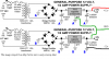
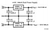
". The first thing yours needs on the left is a +20, a ground, and a -20, which would require the rigging up of the transformers and diodes in a way I've not yet done.

I wanted to make sure connecting two simple rectified sources wouldn't cause a problem with shorting out the transformers or my outlets. Thanks all. I shall give it a try.

The only other thing I'm wondering about is this: I'm using standard PC power cords with three wires: hot, neutral, and ground. Can I take both of the green wires in the cords, tie them together, screw them to the metal box I'm putting these supplies in, and also connect them to the Ground A in my diagram?
 
The only other thing I'm wondering about is this: I'm using standard PC power cords with three wires: hot, neutral, and ground. Can I take both of the green wires in the cords, tie them together, screw them to the metal box I'm putting these supplies in, and also connect them to the Ground A in my diagram?
Yep, that will work.
 
Bottom diode in series with the cap (going to GND) on the -ve supply is the wrong way around. When corrected it should be noted that it will act as a voltage doubler, so the peak input to the -ve voltage regulator will be about -34V volt.
 

Attachments

  • fault_diode.gif
    fault_diode.gif
    2.7 KB · Views: 674
Mods please delete this double post.
 
Posted 3 times? Mods delete please
 
TheOne said:
Bottom diode in series with the cap (going to GND) on the -ve supply is the wrong way around. When corrected it should be noted that it will act as a voltage doubler, so the peak input to the -ve voltage regulator will be about -34V volt.
The voltage at the lower leg of the transformer is only about 15v p-p, due to the diode drops in the bridge. After DC restoration by the diode in question, and rectification, you only get about -12 to -13 volts at the input to the negative regulator. This is with 30 ohms load on each output.
I have to admit that I simulated this to verify it. I'm either too lazy or too stupid to analyze it otherwise. :roll:
 
I was thinking in terms of a light or no load and the danger of max input voltage to the regulator which is -40V. The -ve section will still work as a 1/2 wave voltage doubler where the top will be normal full wave rectification. The dissipation in the -ve regulator will be much higher than the +ve one.

Ron, you have to analyze it over more than 1 cycle to see that the voltages from the caps will add.
 

Attachments

  • -ve_supply.gif
    -ve_supply.gif
    13.8 KB · Views: 667
Here is plot over multiple cycles
 

Attachments

  • -ve_graph.gif
    -ve_graph.gif
    9.3 KB · Views: 645
Yes, of course i've drawed the diode in wrong way! Edited...
BTW: in the real cct. the voltages different...
 

Attachments

  • psu_712.gif
    psu_712.gif
    7.8 KB · Views: 638
TheOne said:
I was thinking in terms of a light or no load and the danger of max input voltage to the regulator which is -40V. The -ve section will still work as a 1/2 wave voltage doubler where the top will be normal full wave rectification. The dissipation in the -ve regulator will be much higher than the +ve one.

Ron, you have to analyze it over more than 1 cycle to see that the voltages from the caps will add.
I was looking at the transformer as 12.6VAC across the terminals. Now I see it says "CT". So what is the voltage across the bridge? Isn't a center-tapped transformer spec'ed at end-to-end-voltage, i.e., wouldn't it be 6.3VAC from CT to each end? Even if the AC voltage is twice what I simmed, the magnitude of the negative output voltage is less than the positive output.
 

Attachments

  • plus-minus_waves.gif
    plus-minus_waves.gif
    6.6 KB · Views: 765
  • plus-minus_sch.gif
    plus-minus_sch.gif
    5.3 KB · Views: 788
Ron, I think the difference is that I assumed that he is using a center tapped transformer and just neglected to show the center tap connected to GND. If it is not a center tapped arrangement then the -ve voltage will be lower. I have not drawn in the C.T and transformer, but set up the incoming AC to act in such a way. Here I have taken the effort to use a transformer and simulated both conditions.

The one is a 12.6V + 12.6V and the last a 12.6V only.
 

Attachments

  • -ve_supply_ct_546.gif
    -ve_supply_ct_546.gif
    15.6 KB · Views: 761
TheOne said:
Ron, I think the difference is that I assumed that he is using a center tapped transformer and just neglected to show the center tap connected to GND. If it is not a center tapped arrangement then the -ve voltage will be lower. I have not drawn in the C.T and transformer, but set up the incoming AC to act in such a way.

NO! - the centre tap must not be connected to ground, it's a bridge retifier circuit, the centre tap isn't used - giving the full 12.6V from both windings to feed a single rail. His original diagram was drawn quite correctly.
 
Status
Not open for further replies.

Latest threads

New Articles From Microcontroller Tips

Back
Top