Continue to Site

Welcome to our site!

Electro Tech is an online community (with over 170,000 members) who enjoy talking about and building electronic circuits, projects and gadgets. To participate you need to register. Registration is free. Click here to register now.

  • Welcome to our site! Electro Tech is an online community (with over 170,000 members) who enjoy talking about and building electronic circuits, projects and gadgets. To participate you need to register. Registration is free. Click here to register now.

Drok meter Issue please help

Status
Not open for further replies.

Master Yoda

New Member
Hello please believe me I have tried everything possible to get this darn thing working correctly.
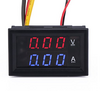
The unit consists of two sets of wires/connectors, the two thin wires coming from the unit are to power it on and that works.
The issue I am having is when I try and set this up with a 12 Volt DC power source and a small 12 Volt light assembly nothing works, it is like it is dead.
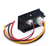
The connection points are very basic that is why this is so embarrassing basically you connect all of the Red colored wires to a common positive and the Black colored wires to the the common negative. That leaves the yellow wire and that is connected to the negative of the light source.
Is this correct????
I would appreciate a fresh set of minds assisting me.
 
Hi Master Yoda,

Welcome to ETO.

Do you have a model number or wiring diagram?
 
Hello again here is more information on this small meter. There are several versions mine does not have a Shunt with it as I has a built in shut that will handle to 10 Amps.
On the back of the meter it has some numbering (DSN-VC288). I am not sure if this will tell much but have more information below as well as images of the unit.
Working current: ≤20mA Display: 0.28 "Two color blue and red Measuring range: DC 0-100V 0-10A Minimum resolution (V): 0.1V Refresh rate: ≥100mS / times Measure accuracy: 1% (± 1 digit) Minimum resolution (A): 0.01A Operating temperature: -15 to 70 ° c Working pressure: 80 to 106 kPa size: 47 × 28 × 16 mm / 1.85 * 1.10 * 0.63 " Net Weight: 19 g Weight: 29 g
 

Attachments

  • Front View.png
    Front View.png
    133.5 KB · Views: 165
  • Back View.png
    Back View.png
    189.4 KB · Views: 192
  • Drawing of Configuration.png
    Drawing of Configuration.png
    614.6 KB · Views: 217
The two thin red/black wires must be wired to a separate power supply (or you should put a 100mA fuse in line with the red wire).
The Thick Yellow wire is Voltage sense (For the Volt meter part of this meter)
The Thick Red wire is + Current
The Thick Black wire is Ground (Common negative).
Remember that this is an AMP meter (red/black) so it should be wired in SERIES with the load that you want to measure
 
Now I am totally confused are you saying the the wiring diagram is wrong?
The wiring of the battery, Dork and out put device is done in Parallel?
For me it is the ability to measure Amps; voltage is of much lesser importance.
 
I have problably same one. In my case it needed aditional isolated power supply.
Winding diagram was wrong.
But as i rember it requiered external current sense resisitor.
 
The one in the photo has a built-in current shunt; the loop of heavy bare wire just behind the connectors.
From a quick search there are several variations of these with the same model number and different wiring.

Assuming yours matches the photo:
Try metering between the thick wires in different combinations - two should have a dead short (the current shunt) and one high or higher resistance to those?
That will at least determine the current and voltage parts.
 
Thank you for the reply!
Having a separate power source is NOT a good option for me.
Yes there is a work around ( Maybe ) but just don' have time for that.
There are better solution available so I chucked the meter in the trash can.

Thanks for taking the time!
 
Status
Not open for further replies.

Latest threads

New Articles From Microcontroller Tips

Back
Top