Continue to Site

Welcome to our site!

Electro Tech is an online community (with over 170,000 members) who enjoy talking about and building electronic circuits, projects and gadgets. To participate you need to register. Registration is free. Click here to register now.

  • Welcome to our site! Electro Tech is an online community (with over 170,000 members) who enjoy talking about and building electronic circuits, projects and gadgets. To participate you need to register. Registration is free. Click here to register now.

Driving a 180V PMDC motor from 230V AC mains

Status
Not open for further replies.

Futterama

Member
Hello forum,

I need a "big" electric motor for a dynamic propeller balancer project where I need to control the motor speed (not accurately to a specific RPM, just up/down), and a treadmill motor seems to be just the thing for my project.
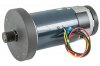
I found a treadmill motor as replacement part at a local store which I think will do fine. The motor only needs to turn in one direction.

The motor is a PMDC type brushed motor rated for 180V and 2HP, which I find is close to 1500W. At 180V average, this is 8.3A.
EDIT: So the 2HP motor rating is mechanical power. And this type of motor is assumed to have an efficiency of 75%. So the max consumed power would not be 1500W but 2000W. At 180V, that would be 11.1A.

My plan was to run it off mains which is 230V AC here. I would add a suitable glass fuse to the circuit.
I would full-bridge rectify the 230V AC to pulsating DC.
Then add a 400V capacitor to even out the ripple.
Then use a PIC controlled PWM through a MOSFET driver to drive a high voltage MOSFET to control the motor. Some optocoupler would need to go in between MOSFET driver and PIC to isolate the mains from the low voltage side.

The PIC microcontroller takes a speed indicating signal, it could be a simple pot and use the PIC internal ADC to read the pot. I will be incorporating a PWM duty cycle limit so I don't over-drive the motor.

The questions I have for this:

1. How much capacitance do I need on the high voltage side to even out the ripples from the rectified AC? The resulting ripple should be low enough not to influence the driving of the motor, I need the motor to run as smooth as practically possible. I was considering to let the PIC read the input voltage and adjust the PWM duty cycle according to the momentary voltage, so as to smooth out the voltage seen by the motor, but I don't know if this would work, I was just brainstorming.

2. Would a MOSFET be the best option for this or should I use an IGBT instead? I have experience with MOSFETs but not with IGBTs. The prices seems similar and the conduction losses are also close, around 20-30W at 10A for the components I can source locally. I'm not yet sure which switching frequency I'll use, so I haven't compared switching characteristics between the two.
MOSFET: FDP22N50N
IGBT: IRG4BC20UDPBF
I can also easily find components with higher amp ratings, and I was also considering TO-247 packages instead, let me know what you think.

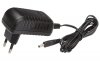
3. Can I use a simple wall adapter power supply for the MOSFET driver and another one for the PIC (if I have the opto between them)? As far as I can tell, those small adapters are fully isolated, so I don't have to worry about voltage potentials and they are cheap and easy to come by. I can even use a 5V USB charger from an old smartphone as the PIC supply. I would need a higher supply for the MOSFET driver e.g. 12V.

I have safety in mind, so I will add isolation where it makes sense depending on how the circuit ends up.
 

Attachments

  • motor.jpg
    motor.jpg
    92.2 KB · Views: 126
  • adapter.jpg
    adapter.jpg
    68.8 KB · Views: 125
Last edited:
Welcome.
This circuit might give you some ideas, I've pinched details from this circuit before, note the supply isnt isolated the motor is at grid voltage, you'd need to beef up the switching tranny and transformer, maybe a push pull topology would be better but its a start:
https://ludens.cl/Electron/latsup/latsup.html
You could modulate the feedback on pin 2 for power control, or add a dedicated fet or ignt for Pwm'ing the motor.
 
Last edited:
SCRs have been used since the 1970s for exactly this type of DC motor control. Not only will the circuit be simpler, but SCRs are significantly more robust than transistors.
By adjusting the firing angle you control the motor speed easily.
 
I did some more searching and I think I found a way to calculate the capacitance for question 1:

http://www.skillbank.co.uk/psu/smoothing.htm

I assume my input voltage can reach 240V AC worst case.
This will give a worst case rectified peak-peak voltage of around 240V * 1.414 = 340V. So a 400V rated capacitor is a good choice.

Worst case low input voltage is assumed to be 220V * 1.414 = 311V.
Assuming the rectified voltage should never get below 180V, which is the motor rated voltage, I can tolerate a voltage drop from 311V to 180V = 131V.
With a 11.1A max load, the capacitor calculation says I need at least 847µF to maintain a minimum of 180V.

So if my PWM input DC voltage swings 131V at 100Hz, this could pose a big problem for my project, it would probably be noticeable on the imbalance graphs.
So I think I either need huge amounts of capacitance (expensive) or I need to go with the idea that the PWM generating PIC should adjust the PWM with the changing input voltage. With a PWM switch frequency in the range of maybe 10kHz, it should be possible to get a stable average DC voltage for the motor.
 
Last edited:
I'll take that a step further: thyratrons, the gas-filled tubes, have been employed since the 1930s to control DC motors.

The SCR belongs to the semiconductor family of thyristors, which is a contraction of thyratron and transistor.........in other words, a solid state thyratron.
 
dr pepper, thanks for the link, I'll have to look through that.

schmitt trigger, you are right, but it will feed the motor in 100Hz pulses, which is what I'm trying to avoid using PWM of a much higher frequency. I'm afraid the 100Hz pulses will create vibrations that could saturate the accelerometer that measures vibration for balancing the propeller, or even mask the propeller vibrations at certain frequencies.
Imagine the propeller balancer running at 3000 RPM. The vibrations from the propeller imbalance should show up as 50Hz vibrations. At this speed the motor would be powered twice each revolution, which I'm afraid could be detectable as vibrations, making it hard to find the actual propeller vibrations.
 
OK; now that I understand your application, I understand that you may require pure DC.

Having said this.....all DC motors have some cogging torque, which is related to the rotor's pole geometry. The cogging torque is what you feel when you turn with your fingers an unpowered motor. The rotor does not rotate continuously but has some distinct steps.... which happen when the rotor poles align to their minimum reluctance position with respect to the magnetic field.

Better motors have lower cogging torque. But even if the motor has significant cogging torque, you can smooth it out with a flywheel between the motor and the load. Think of the flywheel as a "mechanical capacitor". ;)
 
SCRs have been used since the 1970s for exactly this type of DC motor control. Not only will the circuit be simpler, but SCRs are significantly more robust than transistors.
By adjusting the firing angle you control the motor speed easily.
For clarification, an SCR would not be used to control the current to the motor directly right? It would be used between the AC mains and the rectifier in order to control the charge in the rectification smoothing cap?
 
schmitt trigger, yes, I will probably need pure DC or some higher frequency PWM version of it. Thanks for the explanation of cogging, this is also something I'll need to keep in mind, luckily the treadmill motor comes with a flywheel already attached.

ronsimpson, the balancing software does have a RPM gauge but it does not dictate RPM, it just tells the motor controller to spin up to a certain "value" and it is my job to figure out this value beforehand using the software test function and RPM gauge. So yes, I could live with setting the motor voltage to a given value.
 
For clarification, an SCR would not be used to control the current to the motor directly right? It would be used between the AC mains and the rectifier in order to control the charge in the rectification smoothing cap?
If the input voltage/current "pulse" is clipped by the SCR, the capacitor would have to supply the current for even longer, though the load would probably be lower in this case as the total output voltage would be lower. Something to think about, thanks.
 
If smooth operation is needed I would use a simple 555 PWM controller, all you would need is a suitably sized Mosfet on the output.
The Triac controller is a little rougher in operation, especially on the low rpm's.
Basic circuit, requires increasing component and voltage values to suit. Or just Google.
http://www.discovercircuits.com/DJ-Circuits/simplepwm2.htm
If you leave the flywheel attached, always start at zero rpm when powered on.
T.M. controllers do this automatically and have accel built in, due to flywheel inertia.,
Max.
 
Presumaeably you'll be using load cells to measure out of balance, and a processor (pic), you could just before performing a balance do a calibration run, where you run the balancer empty and it stores all of its own unbalanced vibration, then offsets this against the balacing of the prop, so long as the load cells are in their linear range.
A flywheel is a good idea, you'll have some kind of fixture to hold the prop so this will also contribute absorbing parasitic vibrations.
Speaking of old technology and thyratrons, before them there were ignatrons, metal or glass canisters full of mercury, not unlike my avatar, we have got a bit more advanced since then.
 
I have some of these. Input is 220VAC and the put put can be adjusted from 0 to 260VAC.
1) Variac transformer with knob to set speed.
2) Diodes to get DC
3) Capacitors to filter.


upload_2018-1-17_8-46-29.jpeg
 
Last edited:
Welcome.
This circuit might give you some ideas, I've pinched details from this circuit before, note the supply isnt isolated the motor is at grid voltage, you'd need to beef up the switching tranny and transformer, maybe a push pull topology would be better but its a start:
https://ludens.cl/Electron/latsup/latsup.html
You could modulate the feedback on pin 2 for power control, or add a dedicated fet or ignt for Pwm'ing the motor.

That guy's site has a ton of good information and explanation in it.
https://ludens.cl/Electron/Electron.html
 
Presumaeably you'll be using load cells to measure out of balance, and a processor (pic)...
The dynamic balancer thread is here:
https://www.rcgroups.com/forums/showthread.php?2337523-Dynamic-Propeller-Balancer-Build

It uses an accelerometer to measure the imbalance, a Teensy board (kind of a powerful Arduino) for data collection and motor controller interface and it has a user-written application that does the data processing on PC.

I just need more motor power for my bigger propellers than what is depicted in the thread.
 
I have some of these. Input is 220VAC and the put put can be adjusted from 0 to 260VAC.
1) Variac transformer with knob to set speed.
2) Diodes to get DC
3) Capacitors to filter.


View attachment 110321
Yeah, we use these all the time at work for the exact same thing too. The only weakness is you cant automate it onto a closed-feedback loop, but if you don't need that then it's far and away the cheapest and best option. You need big-ass caps though since there is ripple. We use 4mF caps with ours and it's still more ripple than I would like (especially at lower voltages since the ripple is constant and becomes proportionally larger as you turn the voltage down). Well, your flywheel should fix that anyways.
 
Last edited:
Shortbus, yep I've just been reading ludens's site, having trouble with a control loop I'm working on, need to fudge in a pole.

Futterama, yep the teensy is a good board I've used one in a frequency standard project, adafruit do a couple of differently named boards with a similar chip, one has wifi.
 
The only weakness is you cant automate it onto a closed-feedback loop
My largest RF transmitter (20kw) used a variable transformer, with a motor that turned the knob. (I was just controlling the voltage on a grid not the full power) Above 103% power, a relay closed and turned the voltage down. Below 95% power another relay closed and turned the voltage up. Between 95 and 103% no power went to the little motor.
 
I have been doing some more calculations.

According to the balancer build thread, people are using 3000 RPM when balancing their drone props. I don't know if this RPM is applicable for larger props as well. But lets say it does. My currently largest prop is a 2-blade 27x10" which is 27" in diameter and with a pitch of 10". Using the following calculator:

**broken link removed**

spinning this prop at 3000 RPM, requires 0.974 HP or 0.716 kW. This is half the mechanical power of my motor. It is said that the rated motor power is produced mechanical power.
I'll then assume that the motor current is half of full load (11.1A) = 5.55A.

Using this amp value in the capacitor calculator and just tossing a voltage ripple of 10V in there, I get 5550µF.

Of course I want to build a motor controller that can run the motor at full load as well, but I just want a real world example in my considerations.

Using my favorite capacitor manufacturers parametric search, I look for 400-450V electrolytic caps with the highest possible capacitance and ripple current.
The only reference to capacitor ripple current I have come across yet is from this page:

http://www.skillbank.co.uk/psu/ripple.htm

It says as a guideline the capacitor ripple current is twice the load current, so I will need 11.1A * 2 = 22.2A capacitor ripple current at maximum motor load. I want the caps to be able to handle full motor power of course.
I have found these caps:
1000µF 400V 2850mA max ripple current.
820µF 450V 3200mA max ripple current.

To satisfy the ripple current requirement, I would need 8 caps of the 1000µF type. This also satisfies the capacitance requirement for 10V ripple at half motor power. At full motor power, the voltage ripple would be close to 14V with those caps.

To satisfy the ripple current requirement, I would only need 7 caps of the 820µF type, but these would have less ripple current headroom. This also satisfies the capacitance requirement for 10V ripple at half motor power. At full motor power, the voltage ripple would be close to 19V with those caps.

So it seems "easy" to satisfy the ripple current requirements, so I would go for the larger capacitance to get lower ripple voltage. If I choose to add 10 caps of the 1000µF type, I would end up with about 11V ripple at full motor power and only 5.5V ripple at half motor power. That is 1.6% voltage ripple. I don't think this will be noticeable on the balancing waveforms. If so, I can just keep adding caps until it doesn't. When it's this small, I guess the PIC would also have a hard time measuring it accurately for compensation anyway, so I can skip that programming task by using more caps.

EDIT: Caps are pretty expensive, and my programming time is not, so perhaps I'll start out with a smaller cap and the PWM method. Or see if I can make a decouple filter to clean up the 100Hz ripples.
 
Last edited:
Status
Not open for further replies.

Latest threads

New Articles From Microcontroller Tips

Back
Top