Continue to Site

Welcome to our site!

Electro Tech is an online community (with over 170,000 members) who enjoy talking about and building electronic circuits, projects and gadgets. To participate you need to register. Registration is free. Click here to register now.

  • Welcome to our site! Electro Tech is an online community (with over 170,000 members) who enjoy talking about and building electronic circuits, projects and gadgets. To participate you need to register. Registration is free. Click here to register now.

Driving a 12v piezo "screamer" from siren output

Status
Not open for further replies.

NewUser

New Member
This is my plan to enable an existing screamer inside a car to work with a new alarm system, which doesn't have a dedicated 12v output when the alarm trips.

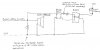
- parallel the siren output with the input of a bridge rectifier
- feed the output of the rectifier to a 4n25 via a current-limiting resistor
- use the output of the 4n25 to control a small 12v relay
- use the relay to drive the piezo screamer

Does this seem OK? I'm guessing if it works then there will be a slight drop in the siren's output?
 
What's a 4n25?
 
I bought all the bits, hooked it up and...no good :(

A digital ammeter, inline between the bridge rectifier's DC output (the AC side being paralleled with the siren speaker) and the photo-LED side of the 4n25 opto-isolator, shows the photo-LED pulls 30mA yet the output transistor won't switch the small 12vdc relay.

If I then hook the photo-LED direct to a 12v power supply (via a resistor selected to also give 30mA current flow) then the 4n25 switches the relay as it should.

Got me baffled. Anyone got any idea of what I'm doing wrong? Or maybe an alternative method of using the fluctuating output to a siren speaker to also control a relay?
 
Can you post a drawing of how you connected all of the components together?

Ken
 
OK here is a rough hand-drawn sketch of the circuit that won't operate the relay.
 

Attachments

  • img4.jpg
    img4.jpg
    59.7 KB · Views: 543
Install a capacitor, say 100uF, on the output of the bridge rectifier to smooth the pulsating DC out.
Note:
The transfer ratio of the 4N25 can be as low as 20% which means you may only have 6ma for your relay. How much current does the relay coil require? There is really no need for an opto-isolator and bridge here since you have commoned the relay's ground source with the siren's anyway. A diode, cap, resistors, and a NPN transistor should be all you need to drive the relay.
 
Last edited:
Thanks, that 100uF cap did the trick! Swapped a diode for the bridge rectifier too which also worked. I'll stick with the opto-coupler rather than a transistor - I bought a heap of 4n25's cheap and I figure I might as well use them for something.

After experimenting with different resistors, I found it took at least 40mA at the photo-LED to get the relay (a small 12v 320ohm unit) to come on, with a voltage of 7.85v@24mA at the coil. Which confirms what you were saying that there is an input/output ratio with the 4n25 opto-coupler. I always thought the output transistors of these were either fully on or off unlike normal transistors. With hindsight, if I'd added a voltmeter across the relay coil I probably would have noticed some voltage there even though the coil wasn't pulling the contacts in. So I've learnt 2 things today!
 
Status
Not open for further replies.

Latest threads

New Articles From Microcontroller Tips

Back
Top