gduprey
New Member
Howdy All,
I'm developing a project that uses a PIC to drive a bunch of highpowered LEDs in a matrix config. The only "interesting" thing is the LEDs are RGB full-spectrum LEDs and I've written a software PWM for each color output. Basically, I'm driving 12 RGB LEDs arranged in a matrix of 2 rows and 6 columns.
I need to pump 40ma at 4.5 volts into the Blue and Green LEDs and 2V @ 40ma into the Red. I'm driving the LEDs in a common anode configuration.
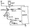
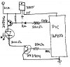
The PIC drives the base of 2N3904 NPN transistors to switch the cathode and each 3904 has a current limiting resistor going from it to the LED. Because of the current demand, the row/anode is being switched using a PNP power transistor. At any given instant, a particular row of LEDs could light up demanding 720ma or so (40ma * 18 LEDs), so I need to use drivers on row and column.
Now, to my actual problem. Because of the voltage drop across the 3904, I can't use a single +5 supply for all the LEDs. I can't get more than about 4.3V across the 3904 and I need 4.5. So I decided to use a +12 supply to drive the LED. Sounds pretty simple.
However, I cannot get the PNP transistors to open/close based on feeding them a +5 or 0V signal. Basically, connecting base to GND or +5 both result in the transistor being on. The only way to turn it off is to connect the base to +12. And I am going through a resistor on the base and I'm confident (now) that I'm not dealing with a blown part.
Note: If everything is drive from a single +5 supply, the PNP behaves as expected, but the resultant current/voltage lights the LEDs too dimmly to be used.
For simplcity and testing, I've switched my power PNP over to a plain old 2N3906 (I'm only driving a single test LED right now, so I'm not overloading it). The +12 and +5 come off the same power supply (I use a 7805 to derive the +5 from the +12). I've attached a simplied schematic of the test circuit I'm now using. Resistor values are appropximate depending on which LED (R, G or B) I'm testing.
I've been doing digital stuff for a long time and even simple buffering for a while and am pretty good at selecting the right parts, calcing the current values, voltage drops, etc I need. But I've not done dual drive with a dual voltage supply before and I suspect I'm definatly missing something.
Could anyone give me a few pointers as to how to make the PNP transistor switch +12 with logic level voltages from the +5 side of the world? I'm definatly stumped and feeling a little silly asking, but I've nopt been able to figure this one out yet :-(
Gerry
P.S. pardon the crudity of the schematic drawing - it was done a little memo pad and I have 0 artistic ability")
I'm developing a project that uses a PIC to drive a bunch of highpowered LEDs in a matrix config. The only "interesting" thing is the LEDs are RGB full-spectrum LEDs and I've written a software PWM for each color output. Basically, I'm driving 12 RGB LEDs arranged in a matrix of 2 rows and 6 columns.
I need to pump 40ma at 4.5 volts into the Blue and Green LEDs and 2V @ 40ma into the Red. I'm driving the LEDs in a common anode configuration.
The PIC drives the base of 2N3904 NPN transistors to switch the cathode and each 3904 has a current limiting resistor going from it to the LED. Because of the current demand, the row/anode is being switched using a PNP power transistor. At any given instant, a particular row of LEDs could light up demanding 720ma or so (40ma * 18 LEDs), so I need to use drivers on row and column.
Now, to my actual problem. Because of the voltage drop across the 3904, I can't use a single +5 supply for all the LEDs. I can't get more than about 4.3V across the 3904 and I need 4.5. So I decided to use a +12 supply to drive the LED. Sounds pretty simple.
However, I cannot get the PNP transistors to open/close based on feeding them a +5 or 0V signal. Basically, connecting base to GND or +5 both result in the transistor being on. The only way to turn it off is to connect the base to +12. And I am going through a resistor on the base and I'm confident (now) that I'm not dealing with a blown part.
Note: If everything is drive from a single +5 supply, the PNP behaves as expected, but the resultant current/voltage lights the LEDs too dimmly to be used.
For simplcity and testing, I've switched my power PNP over to a plain old 2N3906 (I'm only driving a single test LED right now, so I'm not overloading it). The +12 and +5 come off the same power supply (I use a 7805 to derive the +5 from the +12). I've attached a simplied schematic of the test circuit I'm now using. Resistor values are appropximate depending on which LED (R, G or B) I'm testing.
I've been doing digital stuff for a long time and even simple buffering for a while and am pretty good at selecting the right parts, calcing the current values, voltage drops, etc I need. But I've not done dual drive with a dual voltage supply before and I suspect I'm definatly missing something.
Could anyone give me a few pointers as to how to make the PNP transistor switch +12 with logic level voltages from the +5 side of the world? I'm definatly stumped and feeling a little silly asking, but I've nopt been able to figure this one out yet :-(
Gerry
P.S. pardon the crudity of the schematic drawing - it was done a little memo pad and I have 0 artistic ability