Hi,
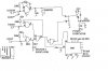
I am trying to find a solution to an old problem I have at home. I have drainage water from the basement going into a cesspit, which contains an immersion pump controlled with a float switch. Sludge collects around the float switch, until it gets stuck, so regular maintenance is required. I was trying to find a better way to do this and eliminate the float switch completely, and found this: Homemade Nixie Clock 2x3 Mux
By the look of it, that's exactly what I need. I don't really need the counting LEDs however, but I can easily remove that part off the circuit. However, there are some missing details in the diagram, and since I'm not really an electronics expert, I don't know how to correct them. So here are my questions:
1. On the diagram there are 4 symbols that look like NAND gates. Am I correct to assume that they are all parts of the same 4011 IC?
2. There are also a number of capacitors with no spec. From what I can get from the photo, is that they are some blue ceramic capacitors. There's also what appears to be one big capacitor. Any idea on what I can use?
3. Before the relay, there's an NPN transistor with no spec. Will any NPN transistor do?
4. There are also 3 resistors without spec. What resistance should I use?
5. Same goes for a number of diodes. Will any diode do?
6. On the top right of the photo, just above the big capacitor, there's what seems to be some 3-terminal component. Any idea what that is?
Sorry for all the questions. I would be very grateful if you can help me out. Thanks!

")