I have a digital wheel speed sensor that reads the speed of a turbine wheel on a turbo. It is set at factory to a peak of 4,666 events per second 4.6KHz (from 0-4666)
I need it to peak at 500 events per second. 500 Hz to be able to read it on the afermarket computer. The software in the computer can only read up to 500hz.
Reduce by 9.333 ~ 10? So what would I need to take this output and get it divided by 10 so it can read effectively through the computer software that runs the car. It is a PWM signal I am sure. I think it is a 12v-13.2v peak to peak. Although it might be a 5v peak to peak. I do not think this will be an issue as amplitude. It is the time frame that needs reducing to be readable.
Stu
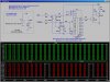
") Pins 13 and 15 must be tied to ground (Vss).
Pins 13 and 15 must be tied to ground (Vss).