I've dreamed up a project and made a design... It seems to work in simulation and I've programmed a 16F628A to produce the output I want... I'd like to get some expert feedback to make sure I'm not doing something patently wrong! It's a long story, but my CO2 injection system for my aquarium has gone haywire twice, causing a depressing fish kill (more so for the fish than for me)... I work with gas cylinders and I've never seen a regulator fail, then work again... I've got my suspicions that my 3 year old (who could give Dennis the menace a run for his money) has been in under the aquarium turning the diaphragm knob! For fail safety, I've installed a lock on the cabinet, but just in case, I thought I should have a means to kill the power to the regulator solenoid should the bubble rate (i.e. the CO2 delivery rate) get too high. Here's the regulator:
**broken link removed**
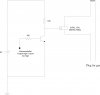
My plan is to use an optical switch OPTEK: OPB819Z:
https://www.electro-tech-online.com/custompdfs/2008/02/OPTEK_3870113.pdf
I was planning to place it around the bubble tube to "count" the bubbles using the microcontroller. My circuit is attached (hopefully). I was planning to sense on RB0 from low to high. I was going to put a 100 ohm resistor from 5V to pin 3 of the OPB819Z and route this to RB0. So if a bubble causes the "loss" of light to the NPN side of the switch, the voltage will go high. The µC will count the number of events each second and if there are more than 2, activate a relay killing power to the solenoid of the regulator thus stopping CO2 flow (and a massive fish kill!).
Any reason this is a poor design? Could it be improved? I'm using MikroC... Here's the code if it helps:
Thanks in advance!
**broken link removed**
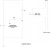
My plan is to use an optical switch OPTEK: OPB819Z:
https://www.electro-tech-online.com/custompdfs/2008/02/OPTEK_3870113.pdf
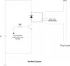
I was planning to place it around the bubble tube to "count" the bubbles using the microcontroller. My circuit is attached (hopefully). I was planning to sense on RB0 from low to high. I was going to put a 100 ohm resistor from 5V to pin 3 of the OPB819Z and route this to RB0. So if a bubble causes the "loss" of light to the NPN side of the switch, the voltage will go high. The µC will count the number of events each second and if there are more than 2, activate a relay killing power to the solenoid of the regulator thus stopping CO2 flow (and a massive fish kill!).
Any reason this is a poor design? Could it be improved? I'm using MikroC... Here's the code if it helps:
Code:
/*
* SIMPLE SERIAL FREQUENCY METER
*
* this program writes one time per second to the RS232 communication line,
* the frequency of the input signal on the RB0 pin
*
* PIC16F628A
* 8 Mhz crystal, HS clock
*
* PORTB.0, in : counter input
* PORTB.1, out : RS232 tx      (rx)
* PORTB.2, in : RS232 rx       (tx)
*
* Author : Bruno Gavand, november 2005,
* The interupt routine used; the rest (including RS232 removed) and further
* modified by TJB; Feb08
*
*/

/*
* RAM variables
*/
unsigned long   cntr ;          // number of RB0 transition
unsigned int    ovrflw ;        // number of timer0 overflows
unsigned char   kill;           // if 1, RB1 changes state

/*
* interrupt routine called 2000000/256 times by seconds :
* the timer TMR0 is increased each 4 clock cycles (quartz frequency is 8 Mhz),
* and overflows when reseting from 255 to 0,
* calling the interrupt procedure with bit T0IF set
*
* also called on each RBO transition, with bit INTF set
*/
void    interrupt(void)
{
	if(INTCON.INTF)
	{
		/*
		* RB0 interrupt
		*/
		cntr++ ;                // inc. transition counter
		if (cntr > 2)
		{
		 kill = 1;
		}
		INTCON.INTF = 0 ;       // clear interrupt flag to enable next call
	}
	else if(INTCON.T0IF)
	{
		/*
		* TIMER 0 overflow
		*/
		ovrflw++ ;              // inc. overflow counter
		INTCON.T0IF = 0 ;       // clear interrupt flag to enable next call on overflow
	}
}

void main()
{
	TRISB.F0 = 1 ;            // RB0 interrupt pin as input
	TRISB.F1 = 0 ;            // RB1 is output
	TRISB.F2 = 1 ;            // RB2 is input - receives reset
	kill = 0 ;                // The kill bit set to 0
	OPTION_REG = 0b11011000 ; // no prescaler

	for(;;)
	{
		cntr = 0 ;              // clear counters
		ovrflw = 0 ;

		INTCON = 0b10110000 ;   // T0IF, INTF and GIE enabled
		if (kill == 1)          // If kill gets set in interrupt....
		   {
		   PORTB.F1 = 1;           // Set PORTB, bit one to high
		   }
		else
		   {
       PORTB.F1 = 0;
		   }
    if (PORTB.F2 = 1)
    {
    kill = 0;               // Reset the kill
    }
		while(ovrflw < 7813) ;  // wait 1 second : 7813 =
								            // 8 000 000 / 4 / 256, rounded up
								            // This modified for 8 MHz crystal!
		INTCON.GIE = 0 ;        // stop all interrupts
	}
}

//
Thanks in advance!