strokedmaro
New Member
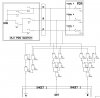
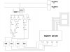
Ok....I built a circuit to control solenoids in a transmission. Normal ops: Solenoids have 12vdc applied all the time and the computer applies a ground to each solenoid in the appropriate combinations for each gear...no problem. I build a circuit to manually control each solenoid for each gear using TIP41's to apply the grounds rather than the computer. This part appears to work.
In manual the car shifts manually like it is supposed to except for a small delay between 1st and 2nd. Im sure its hydraulic and not electric but this led me to build a 7 segment display to indicate what gear was selected.
So, the 7 seg display works flawlessly in automatic (computer controlled)...however it never works in manual even though the gears are shifting normally. I don't understand why it wont work. Im curious to hear what everyone might think it is...The ground for each solenoid comes from the TIP41's Emitter through the collector to the solenoid...Its like the TIP41's are not really "grounding" the solenoids enough to both actuate and indicate the correctly. With the computer grounding the solenoid I read a perfect ground at the 7 seg logic...from Tip41's It drops from 12vdc to about 10vdc at the logic. I will have to post pictures later of the circuit...just wanted to know if the TIP41's are up to the task. 12vdc to solenoid (22 ohm) to ground through TIP41.
THANKS!!!