Hi, I haven't played with transistor logic for too long since school. So I am worried a lot.
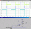
Here is this sensor application schematic, the AMN sensor output will be about 5V, 100uA maximum, I randomly put a few parts, trying to run a few 100mA LEDs, I wonder if you could tell me if any improvement or correction is necessary? Thanks a lot.
( I didn't draw the 12V-5V regulator, maybe I need to increase the eletrolytic cap size for decreasing 12V ripples)
Attachments
Last edited: