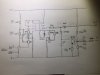
I have a small circuit with a piezo transducer that I can connect an audio signal to. It also has output for sending the signal to a amplifier.
The piezo is like a small drum making sound from the input hitting it.
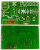
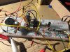
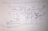
I accidently damaged it and need a new one. I tried to draw a diagram from the circuit board but I'm not sure I got it together correctly. Maybe someone can point out any directly visual mistakes a made?
(Had the transistor the wrong way first, thats because it looks a bit wierd after correction)
Thanks
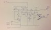
The piezo is like a small drum making sound from the input hitting it.
I accidently damaged it and need a new one. I tried to draw a diagram from the circuit board but I'm not sure I got it together correctly. Maybe someone can point out any directly visual mistakes a made?
(Had the transistor the wrong way first, thats because it looks a bit wierd after correction)
Thanks
Attachments
Last edited:
") )
)