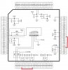
There are massive resources available on this 100 pin chip. I had not intended it for any specific project, but I saw it as an ideal platform, just right for developing routines / drivers for the many peripherals and I/O ( 85 pins on 7 ports ). including its 1Mb flash and 32k ram. The BOB board was ordered from thaishopetc.com via eBay. I had 3 for 7USD and a month for post man... Thc PIC from Farnell UK < 5GBP . The board (2”x2”) has 4 banks of 0.1” holes for double headers and is numbered ,the top side has the 100 .4mm TQFP pads and 6 holes for a ICSP plug ( std PICkit3 layout ) most of the necessary SMD de-coupling, Vpp isolation, Vcap etc are mounted on the lower side .
The photos show the stages of mounting the chip . Needless to say but, the most important is the careful positioning of the chip on the pads, the board was carefully cleaned and a flux pen used to coat the pads, the chip very accurately positioned and held with a clamp device, the flux now a bit sticky helps. A third hand magnifying glass essential here.
Soldering iron was 12w with a .5mm tip. The 4 corner pairs of pins were soldered (tacked) first, the clamp then removed and each side has solder applied to all pins, do it quick, make sure it flows, It will be one long blob ! Wait between sides for chip to cool. !
The excess solder can now be removed with a good quality solder mop using the side of the iron rather than the tip, try to do all the 25 pin at a time dragging the mop braid away from the chip, Use fresh braid each time ( flux braid lightly if necessary ) It should leave just the pins and pads coated … any stray bridges can be rectified individually with braid and iron tip, again wait between sides, clean up with Isopropyl alcohol and a small brush.
Check with DMM on pin holes for shorts check 1-2 then 2-3 etc ( only 100 to do ) add the resistors and capacitors and ICSP pin header, also add links for AVdd (30) and VUSB3.3 (55) to Vdd as these are left floating. ( The PIC won't be detected if you do not power these pins) Check Vdd and Vss is where it should be .
The silicon gods must have been watching over me as MPLABX found the chip, second time of asking... Plan is to mount it on a support board with 3.3 Voltage supply and FTDI serial port .
For a PICaholic like me this exercise was great fun ….
Attachments
Last edited:
