Continue to Site

Welcome to our site!

Electro Tech is an online community (with over 170,000 members) who enjoy talking about and building electronic circuits, projects and gadgets. To participate you need to register. Registration is free. Click here to register now.

  • Welcome to our site! Electro Tech is an online community (with over 170,000 members) who enjoy talking about and building electronic circuits, projects and gadgets. To participate you need to register. Registration is free. Click here to register now.

DIY Low Pass and Mid/High Pass (Bass Blocking) Filters

Status
Not open for further replies.

runslikealpaca

New Member
Hey guys, I am trying to build two filters, as stated above, a low pass one and one that blocks all the lows and allows the mids and highs through.

I really have no idea where to begin, I remember in my electronics class that it had something to do with LR circuits for the low pass and an RC circuit for the high/midpass.

I would like specs to be:
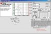
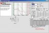
Low Pass: 20-120 Hz
Low Blocking (High/Mid Pass): 120-20k Hz

I am building these two filters to filter two input signals... the filter is between the iPod (for example) and the amp.

Any help would be greatly appreciated!

Thanks everyone

:D
 
Go to the TI website and down load a free program called "FilterPro". It will design high- and low-pass op-amp RC active filters of various orders and gains. I have it downloaded and use it all the time. Write back if you cant find it or need some help with it.
 
Last edited:
i'm running OSX and dont have crossover installed yet. and I was thinking more of a passive filter. much more simple.

thank you very much for the program tho, I'll have to go to my buddy's house to check it out
 
Here is the High and Low Pass Opamp versions as designed with FilterPro. These are way simpler than anything involving inductors...:D
 

Attachments

  • 120HzHP.jpg
    120HzHP.jpg
    173.6 KB · Views: 2,406
  • 120HzLP.jpg
    120HzLP.jpg
    176 KB · Views: 2,186
2 questions:

those op amps would be put between the input signal and the amplifier right?

and my one drawback is that these are powered circuits... is there any way to make a passive filter so i dont need to plug it in??

thanks, sorry im a novice at this stuff
 
Attached is the schematic for two one-pole passive filters to perform the crossover function at 120Hz.

Note that most crossovers for this function are two-pole for faster rolloff but that involves very large inductors to make passive filters at this low frequency. That's why active filters are usually used at audio frequencies.

The resistor values assume a high amplifier input impedance. You may have to measure the amp input impedance and adjust the resistor values accordingly. For example a 10kΩ amp input resistor will shift the frequency about 10%.

The capacitors should be non-polarized film type (mylar or other).
Crossover Filter.gif
 
The huge inductor of a passive sub-woofer filter will pickup mains hum from any nearby mains transformer. A single-pole cutoff is almost useless anyway. You need sharp 3-pole active filters.

The Sallen and Key filter designs usually use equal-value capacitors for the highpass and one resistor double the value of the other. Or equal value resistors and capacitors and the opamp with a gain of 1.6. Texas Instruments Filter-Pro software doesn't know it.
 
where would i ground the schematic that crutschow posted because i am trying to do this filter without a power supply, or do i need one?
 
Look at the response curves of the passive filters. It is almost useless as a filter.
Its response is down -3dB at 120Hz but it still has plenty of output at 1khz (-18dB).
The highpass is the same. It still has plenty of output at very low frequencies.

Crossover filters are usually active so they can have sharp cutoffs with more poles.
 
That makes sense, i guess then how would I wire the opamp's power to have +5 volts and -5 Volts? because i know i need that as its power supply or else it will not cover both sides of the sound wave.

thanks again
 
Any opamp works with a single polarity supply if its input is biased at half the supply voltage and its input, output and feedback resistor to ground are coupled with a capacitor.

Or simply make a dual-polarity power supply.
 
The OPA2244 has even lower power supply current than the lousy old LM358 dual and LM324 quad low power opamps.
But those old opamps have pretty bad crossover distortion so maybe the OPA opamps have even more crossover distortion?

The LM358 and LM324 low power opamps have a very low max frequency at full output level.
The OPA opamps also have a low max frequency (950Hz) at full output level which misses most of the range of audio frequencies.
 
so what would you advise?

if i were to do the battery powered one, how would I hook up the power supplies...? what would i ground the batteries to? i guess i am just unfamiliar with battery powered devices because i learned on ones with power supplies that were plugged in, so there was always a ground "rail" on the breadboard.
 
The common (ground) connection for the batteries (minus side of the + battery supply and plus side for the - battery supply) and any other circuitry would be the common (coax shield, outer part of an RCA connector, or inner-most contact on a phone plug) of the audio connection.
 
Make the circuit on a printed circuit board, stripboard or perforated board. Connect everything that is shown grounded together. The input and output also have ground wires. The two batteries are connected in series and their junction is connected to ground.

Or make the circuit with a single polarity supply as was shown.
 
The OPA2244 has even lower power supply current than the lousy old LM358 dual and LM324 quad low power opamps.
But those old opamps have pretty bad crossover distortion so maybe the OPA opamps have even more crossover distortion?

The LM358 and LM324 low power opamps have a very low max frequency at full output level.
The OPA opamps also have a low max frequency (950Hz) at full output level which misses most of the range of audio frequencies.
Those are some good concerns about frequency response and distortion.

The slew rate is typically 0.1V/µS which gives a maximum frequency response of 16kHz at ±1Vpp, which should be adequate for most casual listening requirements. There isn't usually that much high frequency energy in music.

There's no data in the data sheet about crossover distortion, so I can't answer that concern.
 
what kind of op amp should i be using? is there a lower limit to the amount of voltage that can be used? or are all op amps the same and can run on any voltage?
 
All op amps are different. There are differences in minimum and maximum voltage ratings, current used, frequency response, slew rate, and whether their inputs and outputs operate at the power supply rails (rail-to-rail). You have to look at the data sheets to determine their capabilities and limitations, and then determine the best for your particular requirements.

Suggest you read a tutorial on op amps such as Operational amplifier - Wikipedia, the free encyclopedia to learn more about them.
 
Status
Not open for further replies.

Latest threads

New Articles From Microcontroller Tips

Back
Top