Electro Tech is an online community (with over 170,000 members) who enjoy talking about and building electronic circuits, projects and gadgets. To participate you need to register. Registration is free. Click here to register now.
Welcome to our site! Electro Tech is an online community (with over 170,000 members) who enjoy talking about and building electronic circuits, projects and gadgets. To participate you need to register. Registration is free. Click here to register now.
I have a project due in 4 weeks time. I need to divide two voltages to get a measure of impedance of a DUT. Some one suggested a microproccessor, but I do not know how to use a microproccessor.
Is there any other way of doing this division.
If you want to do analog division you could look into a attenuator with programmable attenuation. The numerator would be the input and the denominator would set the attenuation. Gain of .5 = devide by 2. You might be able to find an opamp circuit for this on the internet. You can use a transistor and resistor as a voltage devider where transistor works as a programmable resistor. If you can find a way to use an opamp to linearize this effect you would have a functional circuit.
All that said it still might be easier to learn about microcontrollers. The solution is trivial in a microcontroller.
How do you get impedance by dividing two voltages? Is the object of the exercise to find the impedance, or is that just part of the problem? What is the problem?
To: Russlk
I am trying to measure the magnitude of the impedance of any Device. I am using a transresistance amplifier to mesaure the current. I need scheme to divide the voltage by the current.
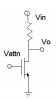
This is what I was thinking of. This schematic doesn't have any biasing will only work for a small range of inputs and only with small signals. With some creative use of opamps you should be able to get better performance. Ive seen this same idea used in the feedback path of an opamp to provide adjustable gain.
The transistor is working like a programmable resistor.
In your transimpedance amplifier, use the unknown Z as the feedback element. Call the known stimulus Vin, and call the resistor from Vin to the summing node Rs.
Then Vout=-Vin*Z/Rs.
If Vin/Rs=1 (or .001, etc.), then Vout=-Z (times a scale factor).
This site uses cookies to help personalise content, tailor your experience and to keep you logged in if you register.
By continuing to use this site, you are consenting to our use of cookies.