I have a project in which I have to design/build an analog distortion circuit.
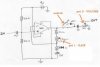
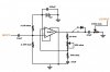
It is my aim to produce (harsh) symmetrical and asymmetrical clipping, with enough gain to also produce near-square output waveforms. I'm trying to keep it as simple as I can. A picture of the circuit I came up with is added as an attachment.
What I'd like to know is exactly how this circuit works (I have an idea which I'll write below) but I'm not 100% so all corrections/explanations welcome!.... ALSO, could this circuit work in a guitar distortion pedal. If not, why not? and how could I adapt it to do so?
*The following is what i think the circuit is doing but correct me if I'm wrong*
The 741 opamp (non-inverting) is used to amplify the input (voltage) signal. There is a pot controlling the gain of the opamp. A 9V battery is being used to power the opamp and provide a voltage divider (ref voltage?) for opamp input... The max output of the opamp will be limited (in amplitude) , hence once the opamp is gained sufficiently, the output signal will be clipped (evenly) top and bottom. A second pot is at the output end of the circuit to allow volume control. There are capacitors at either end of the circuit (coupling), as is the other capacitor(?). And there is a switch that can incorperate a diode into the circuit, which would produce asymmetrical clipping.
I built the circuit on MULTISIM using a signal generator for input signal to the circuit and used an oscilloscope to veiw the output waveform. The appeared to operate as I had hoped (clipping at approx +/- 3.6V and at -0.6V with diode) and the volume pot seems to work.
*Are there any obvious faults with this design?...*
Another concern I have is impedance matching...I read somewhere that the input/output of a typical distortion pedal is high impedance (which the opamp can take, right?, but the output impedance is low?) I'm not sure if/how to match it at the output. What is the result of not or incorrectly matching the impedences? Also, not 100% sure if my capacitor (and resistor) values are viable for this circuit...