Continue to Site

Welcome to our site!

Electro Tech is an online community (with over 170,000 members) who enjoy talking about and building electronic circuits, projects and gadgets. To participate you need to register. Registration is free. Click here to register now.

  • Welcome to our site! Electro Tech is an online community (with over 170,000 members) who enjoy talking about and building electronic circuits, projects and gadgets. To participate you need to register. Registration is free. Click here to register now.

Distortion in Output Signal (BJT Amplifier)

Status
Not open for further replies.

LanceProspero

New Member
upload_2018-4-5_12-4-0.png


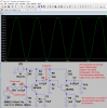
So we were asked to create a cascaded BJT Amp with a minimum gain of around 100v with a ac input of 100mv rms and a freq of 1khz. this was one of my past designs but same problem occurs even thou i achieved the gain of 100v. what seems to be the problem in my output signal?
 
Your circuit has WAY too much gain. The signal at the Q1 collector is is a squarewave, and CC3 and RL are differentiating this into the spike waveform. Put a scope probe on the Q1 collector or emitter to confirm.

ak
 
ic
Your circuit has WAY too much gain. The signal at the Q1 collector is is a squarewave, and CC3 and RL are differentiating this into the spike waveform. Put a scope probe on the Q1 collector or emitter to confirm.

ak
if it does do that, then what will i need to change?
 
At audio frequencies, those capacitors "short out" the emitter resistors because their impedance is much lower. This makes each transistor try to run at it's full gain rather than the gain set by the circuit's resistors. You can look up the gain on the datasheet, multiply the two, and see that with a 0.1 V input the output was trying to make a huge signal, and clipping it to a square wave.

ak
 
Last edited:
The datasheet of a transistor shows its current gain, not its voltage gain.
Here is a simulation showing that each transistor has a voltage gain of about 32 times so their total gain is much too high.
The values for the coupling capacitors are much too small to pass 1kHz at its full level.
 

Attachments

  • transistor amplifier.png
    transistor amplifier.png
    53.2 KB · Views: 105
Status
Not open for further replies.

Latest threads

New Articles From Microcontroller Tips

Back
Top