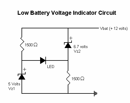
Hello, is there such a thing as a diode that only allows current to flow once it has dropped below a threshold of 13.5 volts DC? Or maybe a transistor or other(very simplistic) circuit I can build? I don't need it to pass much current, only enough to trigger a dashboard light on a car project. It's for an alternator charge indicator light. All I want it to do is sample the battery positive system and keep the dash light off if the voltage is above 13.5v to indicate that the alternator is working. Thanks.
Continue to Site