Continue to Site

Welcome to our site!

Electro Tech is an online community (with over 170,000 members) who enjoy talking about and building electronic circuits, projects and gadgets. To participate you need to register. Registration is free. Click here to register now.

  • Welcome to our site! Electro Tech is an online community (with over 170,000 members) who enjoy talking about and building electronic circuits, projects and gadgets. To participate you need to register. Registration is free. Click here to register now.

Diode query

Status
Not open for further replies.

Tricati

New Member
I’ve problems with the running of my 20 yr old motorcycle and when checking out the electrical components, found the readings of the two diodes (number 11 on the diagram) to be different to the ones stated in the manual; namely, the manual states ‘infinity’ checked in one direction, and 0 - 1 ohm with the tester’s leads reversed. The readings I obtained were ‘infinity’ and 1.8 M ohms which would indicate, if the manual figures are correct, the diodes have broken down (?). The manual, although extremely comprehensive, has one or two items that are questionable. Can someone comment on the diodes’ readings please, and referring to the diagram, what are the purpose of the diodes? Thanks
 

Attachments

  • E3ECBB6B-B261-4C5D-82C6-13806F355C85.jpeg
    E3ECBB6B-B261-4C5D-82C6-13806F355C85.jpeg
    1.2 MB · Views: 268
A normal, good, diode has a voltage drop when conducting, typically around 0.6 - 0.7V

The conducting or "forward" reading you get when using a meter in resistance mode will vary tremendously between types of meter.
I don't offhand know of any that would show zero ohms with a good diode!
Mine shows around 1.6 MOhms on a perfect brand new diode (and infinity the opposite direction).

Ideally, use a meter that has a specific diode test function.
Or in your bike, as it is a DC system, measure the voltage across the diode when it's in use and see if it's ever much more than 0.6V whilst the anode is positive of the cathode.
(The cathode end should be marked with a single band or bar; right hand side of the diodes in the drawing).
 
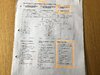
The diodes let the current in one direction but not the other. On the motorbike the ignition is allowed to run if the gearbox is in neutral or the side stand is up. That could be done by putting the two switches in parallel. However that would make the neutral light come on when the side stand is up. The diode lets the current from the CDI go to either switch, so either switch will let the engine run. When the side stand is up and the gearbox is not in neutral the diode stops the current from the neutral light going through the side stand switch.
motorbike.png


When the neutral switch is on, current will flow along the orange route, allowing the starter and the ignition to operate. The current flows through the diode, the upper one in the diagram. (The neutral light will illuminate, but that doesn't need the diode)

When the stand switch is on, the current cannot flow along the blue path, because that would be going through the diode the wrong way. The neutral light will not illuminate because the diode will block the current. (Starting and ignition will be allowed, but that doesn't need the diode)

Similarly, starting is allowed if the stand is up and the clutch is disengaged. Current from the starter safety relay (5) flows though switch 8 (clutch) and switch 9 (stand) and allows the starting. The other diode, the lower one in the diagram, will stop the current from the neutral light from also going through those two switches, so the neutral light stays off.

You can test the diodes as follows:-
Turn on ignition. Select neutral. Leave stand down. Do not pull the clutch lever. Try to start engine. If it cranks and runs, then both diodes conduct in the forward direction, which is correct.

Stop engine. Turn ignition on. Select a gear. Lift stand and pull the clutch lever. If the neutral light light stays off, then both diodes are blocking in the reverse direction which is correct.

As a separate test, if you turn on the ignition but don't start the engine, select neutral and leave the side stand down, the voltage across the stand switch should be about 0.6 - 0.7 V.
 
Many thanks Diver 300. I always wondered how the system worked! I’m guessing maybe you’re a motorcyclist yourself. Having explained the system thoroughly, I feel slightly embarrassed asking an additional query - which may be electrically connected.
The bike’s a single cylinder, 650cc Aprilia Moto 6.5 with a Rotax engine. The bike was running okay until Spring of last year when after approx 20 mins on the road the engine suddenly died, only to restart again when the engine was cold. This repeated itself on the next two outings with roughly the same amount of time on the road.
The following were replaced: spark plug, ht lead, plug cap, ignition coil, voltage regulator and as yet to be tried, an expensive CDI unit.
I’m pretty sure some of the above items were probably needlessly replaced. All the wiring, connections and relevant voltages were checked.
Clean fuel was getting through to the carb - which was dismantled and thoroughly cleaned - and the second and third outings were made with the fuel tank cap open- in the event a vacuum was being created.
Your opinion would be much appreciated....and many thanks again regarding the diodes; which by the way are probably okay (?) and sounds as though they wouldn’t cause the engine to stall anyway. Regards
 
I have owned a motorcycle, but that was quite some time ago. I think that my electronics knowledge is of more use here.

I don't think that the diodes would cause the engine to stall. If the bike cuts out when the side stand is down and the gearbox is not in neutral, that means that the side stand switch is working, and the diodes can't stop the engine working. If the bike would not start or run in neutral if the stand was down, or the neutral light came on when the stand was down, then the diodes could be a problem.

With all the items that you've changed, it sounds like the problem is the CDI unit, but there is also a pick-up coil, according to this diagram:-https://www.moto65.de/pics/schaltplan_regler_original.gif

Did the engine cut out at speed, or when the engine was at idle? If it's at idle, it could be the pick-up coil. On another vehicle, a car with electronic engine management, I have heard of the pick-up coil getting weak when it is a few years old. The voltage becomes too small when hot. The voltage is more with faster engine speed, so you will first notice the problem when hot and running slowly.

On the car, the engine would not start when hot, when the cranking speed was only about 200 rpm, and the idle speed was about 800 rpm, so there was lot more voltage available when the engine was running.

I don't know what the cranking and idle speeds would be for a motorbike.
 
I didn’t realise the pick-up, as it’s termed in the the manual, is actually a coil. I’ve inspected it and checked it’s resistance as per the manual, which was within acceptable limits. As you mentioned though, it could be faulting when getting hot, and on all three occasions the engine cut out when coming to a standstill at traffic lights and embarrassingly at a busy traffic island!....and incidentally, the battery was replaced too.
My other two mounts are 60 + yr old Brit bikes with uncomplicated magneto ignition, which apart from checking the points every 3,000 miles, continue to give uninterrupted service!
Many thanks again for sharing your expert knowledge and help.
 
My suggestion would be to connect an ac voltmeter (or a multimeter set to ac volts) to the coil. The start the bike and measure the voltage at idle. Then wait for the engine to get warm, and see what the voltage across the coil is at idle. I don't know how much the voltage should reduce, but if it's less than about half of what it is when cold, I would suspect the pickup.
 
Thanks Diver 300. I’ll certainly try that as soon as possible and will let you know outcome.
Kind regards. Tricati
 
Hello again Diver300. I’ve only just been able to try your suggestion regarding the pick up on my Aprilia Motorcycle. You advise that I check the voltage at the pick up with engine running when cold and the same when hot to determine if there’s a voltage difference. Will I need to strip back some of the insulation though to gain access to the pick up conductors with the voltmeter, as disconnecting at the connector ( from pick up to CDI unit) will prevent the motor from starting....and running. I may be overlooking the obvious...your comments would again be appreciated. Tricati
 
To measure voltage, you could use a sharp object, like a pin, to pierce the insulation, or to poke into the connectors. There are special sharp probes for multimeter leads that are designed to access insulated wires.

You could take a single strand of flexible cable, and insert it into the connector, and reassemble. A single strand could allow the connector to be reconnected, and would let you measure the voltage.
 
Hello Diver300. Connected the voltmeter, which showed just over 0.4 volts ac when cold and didn’t deviate when reached running temp. Unfortunately the engine stopped again at just about the same interval of running, namely 15mins. ...and this with a new CDI unit: so it’s back to the drawing board...and many thanks for your help. Tricati
 

Attachments

  • 5040856A-8085-41FC-A530-5D48582F8D31.jpeg
    5040856A-8085-41FC-A530-5D48582F8D31.jpeg
    1 MB · Views: 250
I like your break-in connector. It looks like it worked well.

Your Fluke 77 has a diode test function. When you turn the control to the diode test the display will show the voltage drop. If the voltage drop is consistent with a diode, the meter will give a short beep. If the voltage is lower than that, the beep will continue until the connection is broken.

Have you tried one of these:- https://www.ebay.co.uk/itm/Silverli...and=Silverline&_trksid=p2047675.c101195.m1851

That will check if it is the spark that is failing.

Did you measure the pickup voltage when cranking?
 
Status
Not open for further replies.

Latest threads

New Articles From Microcontroller Tips

Back
Top