Continue to Site

Welcome to our site!

Electro Tech is an online community (with over 170,000 members) who enjoy talking about and building electronic circuits, projects and gadgets. To participate you need to register. Registration is free. Click here to register now.

  • Welcome to our site! Electro Tech is an online community (with over 170,000 members) who enjoy talking about and building electronic circuits, projects and gadgets. To participate you need to register. Registration is free. Click here to register now.

Diode ID help please

Status
Not open for further replies.

1084st bloke

New Member
Hi there, I have a Commodore 1084ST computer monitor I'm trying to repair and would appreciate some help identifying a component. The problem is exacerbated by the lack online of any service manuals, so I'm currently drawing my own circuit diagram (it's going slowly). I have basic electronics experience and have repaired a few vintage 8-bit computers and the like. I haven't worked on a CRT before (I understand how to discharge the tube).

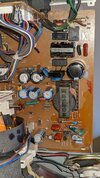
The monitor had a fault where it would blow the internal fuse immediately on powerup. So I traced that back to a shorted MOSFET on the switch mode power supply. The replacement MOSFET blew immediately, so I looked further back and found that a TDA4605 controller was pretty much shorted between the supply and earth pins.

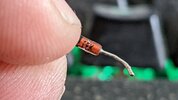
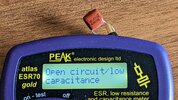
So I've replaced the MOSFET and IC now, but I thought I'd have a look on the supply pin before I ruined that IC and another MOSFET. There's what I think is a diode protecting it, but I can't identify it. I think the text is 1N4. I have a strip of 1N4148 diodes and wondered if it'd be appropriate to substitute.

I should add that I've checked the bridge rectifier and that's fine, as are the filter caps and other components nearby. I understand the monitor has some power supply protection from problems closer to the back of the tube, so at this point I'm mainly concerned with getting the power LED on. The person I bought it from said "it just turned off" so my guess is it's purely a PSU problem.

Here's the 4605 datasheet - https://www.alldatasheet.com/datasheet-pdf/pdf/25064/STMICROELECTRONICS/TDA4605.html

PXL_20220426_124005253.jpg
 
Your mistake was in changing just the FET - you MUST change all faulty components, or it will just blow everything again, and possibly cause more damage.

The monitor is actually made by Philips, and just badged Commodore, I 'think' mine at home is a Philips one, and I'll check when I get home for the model number.
 
I think the text is 1N4. I have a strip of 1N4148 diodes and wondered if it'd be appropriate to substitute.
Flip over the diode to see the rest of the part number. Based on 1N4, it can be either a small signal diode or a zener diode. These are very different in operation, so the rest of the part number is important.

ak
 
Your mistake was in changing just the FET - you MUST change all faulty components, or it will just blow everything again, and possibly cause more damage.

The monitor is actually made by Philips, and just badged Commodore, I 'think' mine at home is a Philips one, and I'll check when I get home for the model number.

Thanks, it isn't a Philips, it has a Philips tube but the board is very different from anything else with the same model number (there are lots of variations of the 1084, the 1084ST is from the very end of Commodore). Some people think it's a Malaysian company called Likom. I've emailed them for a diagram but I don't expect a reply.
 
Flip over the diode to see the rest of the part number. Based on 1N4, it can be either a small signal diode or a zener diode. These are very different in operation, so the rest of the part number is important.

ak

It's hard to see, this is the best I could get. I'm hoping someone familiar with the IC could suggest an appropriate value.
 

Attachments

  • PXL_20220426_141218376.MP.jpg
    PXL_20220426_141218376.MP.jpg
    3.6 MB · Views: 193
Back home now, my monitor is a Philips CM8833, and unfortunately doesn't use a chip in the PSU - but from what you've just posted it probably wouldn't help anyway.

The data sheet you linked to was pretty useless, as it doesn't give an example circuit - but here's one:


I've repaired hundreds of TV's based on the TDA4605 (and many hundreds more based on other chips), as I mentioned before it's absolutely essential that you replace all faulty parts before switching at on, or they all just blow again, often causing further damage.

I was repairing so many I used to make up repair kits, of all the common parts that failed - and simply blanket change all the parts in the 'kit'.

From the circuit I posted above, I would suggest changing (or at least VERY carefully checking) - the TDA4605, T1, D1, D3, R13, C2, C6 (and check C1 - these go O/C occasionally, and commonly blow the PSU, depending on the set - Grundigs always did, Tatungs never did, yet the circuit was pretty well identical?). I'd also check R4 and R8, R1 is a component that fails, but that's just the start-up resistor, and shouldn't blow the supply. You might also check R11, as it's in the range where resistors commonly fail.

You could also check the secondary rectifiers, to see if they are short - do it in circuit, as it will then check if there's a short elsewhere on the secondaries - these shouldn't blow the PSU, it should self limit, but weird things happen.

A fairly unlikely fault could be the transformer itself, but this is rare - and usually only happens to specific makes and models, which obviously don't use a very good transformer - I've known them O/C, S/C windings, and even S/C between windings - but it is rare.

BTW, you're asking about the diode - is it faulty?. Assuming it's D3 off the circuit above, then it's just a DC rectifier feeding the voltage setting pot, D1 is the supply for the chip (and a slightly bigger fast recovery diode).
 
I replaced that diode (which I'm presuming is a 1N4148 Zener) as it tested identically to new ones I have, although I only did a basic meter check.

But I've continued to check and this cap, which is in that immediate area (difficult to describe without a diagram but one side is on a transformer nearby and it connects to the IC through another diode) isn't well.

Just to check, because the dot on these caps is confusing me. I have another elsewhere in the circuit that is marked with .33, reading at about 38uF (5% tolerance). So with the extra zero, this one should be 0.33uF?
 

Attachments

  • PXL_20220427_151609804.MP.jpg
    PXL_20220427_151609804.MP.jpg
    3.6 MB · Views: 175
I also have a 2.2nF cap too small for me to measure with anything I have, so I'm just going to replace the lot and check other resistors etc.
 
I replaced that diode (which I'm presuming is a 1N4148 Zener) as it tested identically to new ones I have, although I only did a basic meter check.

But I've continued to check and this cap, which is in that immediate area (difficult to describe without a diagram but one side is on a transformer nearby and it connects to the IC through another diode) isn't well.

Just to check, because the dot on these caps is confusing me. I have another elsewhere in the circuit that is marked with .33, reading at about 38uF (5% tolerance). So with the extra zero, this one should be 0.33uF?

It's clearly marked as 0.033 - which would be 33nF (or 0.033uF) - but these aren't the kind of components which fail and cause PSU's to die. Having repaired thousands, I've never changed anything like that, and probably never even tested any of them?.

I se on the circuit I posted above that C4 is a 33nF capacitor.

As already mentioned, the 1N4148 is a small signal diode, and not a zener, there's unlikely to be a zener in the PSU.

Have you tested the components I suggested? (in post #6), those are the most likely to give problems.

I'm slowly going through them (I had other things to do today). The circuits are quite different. I'll get there though.
 
Tested most of everything now, except 5-6 hard-to-see to components I've yet to get to. I'm still trying to find RP19 (RP20 is the highest I can see) but it may not exist. Every component so far seems fine but I've noted that one small resistor on the secondary side of the transformer should be 180 ohms, but is reading as 100 ohms out of circuit. I'm not sure where it would be if it were on your diagram, well over to the right I imagine (the components on this board are numbered according to their distance from mains).
 

Attachments

  • PXL_20220428_132117188.jpg
    PXL_20220428_132117188.jpg
    1.3 MB · Views: 174
Tested most of everything now, except 5-6 hard-to-see to components I've yet to get to. I'm still trying to find RP19 (RP20 is the highest I can see) but it may not exist. Every component so far seems fine but I've noted that one small resistor on the secondary side of the transformer should be 180 ohms, but is reading as 100 ohms out of circuit. I'm not sure where it would be if it were on your diagram, well over to the right I imagine (the components on this board are numbered according to their distance from mains).

Are you sure that's the value the colour code on the resistor gives it?, it would be EXTREMELY rare for a 180 ohm resistor to drop down to 100 ohm (thinking winning the lottery jackpot every couple of weeks). Follow the tracks, and tell us which component on the circuit above it would be, or at least where each end goes. I presume you're assuming the second coloured band is grey?, it could just as easily be black.

I say this everytime in these types of threads - you don't repair things by randomly removing components and trying to test them out of circuit, you do so by fault finding and experience.
 
I think you're right about the resistor's value, it's too much of a coincidence. But I'm not randomly testing components, I'm being methodical and testing everything in the area, working outwards from the IC. And the values I'm recording I'll put online so that others can find them when they search for issues with the same model of monitor.

I don't have much experience but this is how people learn. I like to DIY everything myself, I've done most of my house this way, I fix my car myself, service my bikes myself, and repair electrical equipment I own myself.

I'm also beginning to wonder if one of the coils in the transformer is shorted, which isn't something I think I can test for. And who knows if I can find a replacement, not having a circuit diagram.

/edit: just occurred to me that if I can't find anything problematic on the primary side of the transformer, I could remove the transformer and attempt to power up?
 

Attachments

  • PXL_20220423_103724196.jpg
    PXL_20220423_103724196.jpg
    2 MB · Views: 170
Last edited:
I think you're right about the resistor's value, it's too much of a coincidence. But I'm not randomly testing components, I'm being methodical and testing everything in the area, working outwards from the IC. And the values I'm recording I'll put online so that others can find them when they search for issues with the same model of monitor.

That's randomly testing components :D

I don't have much experience but this is how people learn. I like to DIY everything myself, I've done most of my house this way, I fix my car myself, service my bikes myself, and repair electrical equipment I own myself.

I'm also beginning to wonder if one of the coils in the transformer is shorted, which isn't something I think I can test for. And who knows if I can find a replacement, not having a circuit diagram.

As I mentioned above, transformer failure does happen, but it's very rare, and in my considerable experience only occurs on certain makes and models, where there was obviously a design flaw in the transformer - from I can remember, out of the thousands of PSU's I repaired, I used to only stock two transformers, interestingly both were for satellite receivers.

/edit: just occurred to me that if I can't find anything problematic on the primary side of the transformer, I could remove the transformer and attempt to power up?
Power up what?, and how?.
 
Power up the power supply without a load, to try and isolate whatever the issue is to before or after the transformer. But I don't know how much interaction there is between the psu and the rest of the board.

BTW I have found examples online of the same monitor where the TDA4605 has failed seemingly of its own accord, but they don't elaborate on the nature of the failure. Eg this is the exact model I have
You can't really power the primary without the transformer, as the chip is powered by the transformer (D1), plus there's feedback to the chip as well (D3).

Do you have an oscilloscope?, you 'may' be able to test it to some degree - bearing in mind that the primary is live mains, and the scope is earthed, so will go BANGGG!!! if you connect them. Usual solution is to feed the TV via an isolation transformer.

But if you've got a scope, you could test the transformer anyway:


But that antique method does rely on a timebase output from the scope, otherwise you'd have to build a pulse circuit to make it 'ring'.
 
Status
Not open for further replies.

Latest threads

New Articles From Microcontroller Tips

Back
Top