Continue to Site

Welcome to our site!

Electro Tech is an online community (with over 170,000 members) who enjoy talking about and building electronic circuits, projects and gadgets. To participate you need to register. Registration is free. Click here to register now.

  • Welcome to our site! Electro Tech is an online community (with over 170,000 members) who enjoy talking about and building electronic circuits, projects and gadgets. To participate you need to register. Registration is free. Click here to register now.

Diode Bridge

Status
Not open for further replies.

tom_pay

Member
Hi Guys,

For a circuit I'm making I need a 30 A diode, however I cannot find a 30 A diode in any of my local shops.

If I got a 30 A Bridge rectifier and wired up just one diode, could this one diode withstand 30 A?

The circuit has a 20 A fuse in it, so the 30 A diode is very conservative.

Tom
 
Hi Guys,

For a circuit I'm making I need a 30 A diode, however I cannot find a 30 A diode in any of my local shops.

If I got a 30 A Bridge rectifier and wired up just one diode, could this one diode withstand 30 A?

The circuit has a 20 A fuse in it, so the 30 A diode is very conservative.

Tom

hi,
If you considered the -V terminal as the 'ac' input, strap the two usual 'ac' inputs together as the output this would put two diodes in parallel.

One diode of the bridge should be fine at 30A, if the bridge is rated at 30A
 
Please post a schematic?

I know diodes don't share current very well but two 20A diodes should be able to carry 30A.
 
Schematic Image

Here is what I want to do.

The diode bridge is rated for 30 A so will the single diode also be?

Thanks

Tom
 

Attachments

  • Bridge..JPG
    Bridge..JPG
    19 KB · Views: 724
That should be fine but it might not be needed, you might be able to use a single, smaller diode but since you haven't posted a schematic of the circuit you want to use the diode in, we can't tell you.

EDIT:

It's also possible to parallel two of the diodes which will cut the voltage drop, reduce the power dissipation and increase the reliability.

You'll also be able to use a bridge with a lower current rating - 20A should do for 30A.
 

Attachments

  • Bridge rectifier&#3.PNG
    Bridge rectifier&#3.PNG
    3.1 KB · Views: 1,359
Last edited:
It's also possible to parallel two of the diodes which will cut the voltage drop, reduce the power dissipation and increase the reliability.

You'll also be able to use a bridge with a lower current rating - 20A should do for 30A.
You can parallel diodes but I would not count on being able to use two 20A to carry 30A. One diode will tend to initially carry slightly more current than the other, which will cause it to heat to a higher temperature. This will lower its forward drop and cause it to carry even more of the load. Thus one diode will tend to hog the current. Better to have each diode rated at least for the maximum current you want to carry.
 
They aren't descrete diodes you know!

I know that ,but as the diodes are on the same bridge, the chances are they'll be cut from the same die, so will be very similar and as they're all in the same module, they will all be at practically the same temperature.

In short, I disagree, I think they'll share the current pretty well, 2x20A diodes carrying 30A was a conservative estimate.
 
Last edited:
You can parallel diodes but I would not count on being able to use two 20A to carry 30A. One diode will tend to initially carry slightly more current than the other, which will cause it to heat to a higher temperature. This will lower its forward drop and cause it to carry even more of the load. Thus one diode will tend to hog the current. Better to have each diode rated at least for the maximum current you want to carry.

This phenomenon is not as much of a problem as is commonly believed. There is some decrease in current sharing due to differences in diodes, but it is minimal.

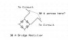
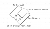
Here is the result of an experiment. I took 2 identical 20 amp diode bridge assemblies, the type where individual diodes are mounted in a package, electrically isolated from the package, but on the same thermal substrate, which is intended to be mounted on a heatsink. I did not mount the assemblies on a heatsink.

I used a large 2 kW transformer, with a 120 VAC primary and a 12 VAC secondary. I connected one diode from each assembly in series with a .001 ohm shunt to monitor current, connected the 2 diodes (plus shunt) in parallel, with heavy wires, and placed the combination across the secondary of the transformer. With a variac on the primary, I could gradually increase the current through the diodes which were simply shorted across the secondary. I avoided any excess resistance in series with the diodes, which might act as ballast, tending to equalize currents. I captured scope images of the diode currents, with different colors for the two currents..

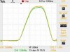
I first increased the diode currents to about 30 amps peak, starting with cold (at room temperature) diodes, and capturing the current traces before the diodes had time to warm up significantly. The first image shows this situation.

I then waited several minutes until the diode packages were blazing hot, about 120 degrees C according to a thermocouple measurement. The second image shows this result.

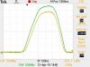
Finally, I allowed the diode assemblies to cool back down to ambient. Then I used a hot air gun to heat ONE of the diode assemblies to about 100 degrees C, with no current in the diodes. Then I quickly applied about 30 amps peak to each diode and captured the scope trace. This result is shown in the third image.

It can be seen that there is good current sharing between two diodes in two different packages, even when the diodes are allowed to heat up without heat sinking, at fairly high currents.

Even with the extremely unfavorable case of pre-heating one diode to 100 degrees, the other remaining at room temp, the degree of mismatch in currents is not much, 29 amps vs. 33 amps peak.

As Hero999 said, if the diodes are all in one package, they will tend to be matched, and the thermal substrate they are mounted on will not allow any one diode to get much hotter than any other. And, the normal resistance of connecting wiring will tend to ballast the diodes; I was careful to avoid this effect as much as possible by using short, heavy, connecting wires.

The problem you describe is a non-problem for this type of bridge rectifier assembly. A user can safely use two diodes from the same bridge in parallel, with the effective current rating doubled. Proper heatsinking is required, but considering that a bridge rated for 20 amps is rated that way with all 4 diodes carrying current, if only two diodes are used I would think that perhaps even somewhat more than 20 amps will be within ratings.
 

Attachments

  • StartCool.jpg
    StartCool.jpg
    43.4 KB · Views: 383
  • Self_Heat.jpg
    Self_Heat.jpg
    43.4 KB · Views: 339
  • HotAirGun.jpg
    HotAirGun.jpg
    26.3 KB · Views: 331
The problem you describe is a non-problem for this type of bridge rectifier assembly. A user can safely use two diodes from the same bridge in parallel, with the effective current rating doubled. Proper heatsinking is required, but considering that a bridge rated for 20 amps is rated that way with all 4 diodes carrying current, if only two diodes are used I would think that perhaps even somewhat more than 20 amps will be within ratings.
Well, your experiment certainly would indicate that current sharing is not a significant issue with paralleling the same diodes when thermally connected.

But the rating for a bridge rectifier is for two diodes in series alternately carrying the current in a full-wave rectifier at a 50% duty-cycle. So I wouldn't put more than 20A through a 20A rated bridge.
 
But the rating for a bridge rectifier is for two diodes in series alternately carrying the current in a full-wave rectifier at a 50% duty-cycle. So I wouldn't put more than 20A through a 20A rated bridge.

The rating of a diode is ultimately determined by temperature rise. If only two of the diodes are active, the heat that would have been generated by the other two diodes is absent, leading to a somewhat reduced temperature rise, and somewhat larger current capability in the two that are used. This certainly won't allow a doubling of the current capacity, but it definitely means that you can get the full rated current per diode even with a tiny amount of unbalanced current sharing.
 
Interesting.

This discussion often crops up with LEDs, have you done any experiments?

I imagine it will be fine as long as the LEDs are all the same part number and they're derated a bit.
 
The rating of a diode is ultimately determined by temperature rise. If only two of the diodes are active, the heat that would have been generated by the other two diodes is absent, leading to a somewhat reduced temperature rise, and somewhat larger current capability in the two that are used. This certainly won't allow a doubling of the current capacity, but it definitely means that you can get the full rated current per diode even with a tiny amount of unbalanced current sharing.
No, the power is about the same either way. Since the diodes in a bridge rectifier are normally conducting only 50% of the time, than the heat generated by the four diodes in a 20A bridge rectifier circuit is roughly the same as two diodes conducting 20A continuously. Thus there would be no significant difference in power or derating for either configuration.
 
But if the diodes are rated for higher currents at 50% duty cycle, lower currents mean a lower voltage drop and power dissipation. The rating will also be for an RMS sinewave which will have a higher peak current and therefore higher peak voltage loss.
 
No, the power is about the same either way. Since the diodes in a bridge rectifier are normally conducting only 50% of the time, than the heat generated by the four diodes in a 20A bridge rectifier circuit is roughly the same as two diodes conducting 20A continuously. Thus there would be no significant difference in power or derating for either configuration.

I didn't get the impression that the OP intended for his diode to be conducting continuously (DC, in other words). If the diode is rectifying AC, then his one diode would be conducting 50% of the time. If the other two diodes in the bridge aren't conducting at all, then the the heat they would normally generate will be missing. Do we know what his application is?
 
It is a secret, and he won't reveal us, because he is goint to patent it and we all are going to steal his application. =D

I don't see any problems using an isolated diode from a 30A bridge. Each diode in a bridge is rated to at least the bridge's rating.
 
Last edited:
Status
Not open for further replies.

Latest threads

New Articles From Microcontroller Tips

Back
Top