Continue to Site

Welcome to our site!

Electro Tech is an online community (with over 170,000 members) who enjoy talking about and building electronic circuits, projects and gadgets. To participate you need to register. Registration is free. Click here to register now.

  • Welcome to our site! Electro Tech is an online community (with over 170,000 members) who enjoy talking about and building electronic circuits, projects and gadgets. To participate you need to register. Registration is free. Click here to register now.

Diode as a ripple source.

Status
Not open for further replies.

electricity86

New Member
Hello there.
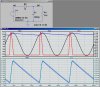
I read about power supplies and it was said there that its not good that the time the diode remains ON will be long since the diode causes ripples in the output voltage.

The PSU I read about was half wave rectifier, and full wave rectifier, that use a filter capacitor in the output.

Why does the diode cause ripples to the output voltage?
 
Without diode you have 100% ripple - pure AC.
 
The diode does not cause ripple.

Ripple is a result of the AC waveform going through 0V every half cycle.
 
Here is what they said:

"The slope of this line increases as the current increases,
bringing point c lower. Consequently the diode
conduction time (c-d) increases, increasing ripple.".

diode-jpg.29514


So the ripple here is the c-d part of the graph?
How do you condier the b-c line, if its not part of the ripple?

This c-d line is crossing the zero every complete cycle, not half cycle, is it still considered to be a ripple?
 

Attachments

  • diode..JPG
    diode..JPG
    14.5 KB · Views: 789
Last edited:
Hello there.

Why does the diode cause ripples to the output voltage?

The diode doesn't cause the ripple. The ripple results from the fact that the filter capacitor gets a momentary recharge every 16.6msec (or 20msec if 50Hz), and then it is up to the capacitor to supply the load current until it gets another recharge during the next AC peak when the diode conducts to refill the capacitor. The larger the capacitor, the less the ripple....

Look at the attached sim. Note the peak diode current as compared to the load resistor current and its duty cycle.

Exercise for student: How big would the filter capacitor have to be to reduce the load ripple voltage to < 0.5V? Why would you rather use a full-wave rectifier?
 

Attachments

  • Rectifier.jpg
    Rectifier.jpg
    356.5 KB · Views: 1,076
So the ripple here is the c-d part of the graph?
How do you condier the b-c line, if its not part of the ripple?

This c-d line is crossing the zero every complete cycle, not half cycle, is it still considered to be a ripple?
The ripple is simply the peak-to-peak difference between the two voltage levels. It includes c-d and b-c.
 
Here is what they said:

"The slope of this line increases as the current increases,
bringing point c lower. Consequently the diode
conduction time (c-d) increases, increasing ripple.".

The diode conduction time is constant, depending on mains frequency.

Think logic! What is changing in the circuit? - the diode, mains frequency or the load current?

If the diode remains the same and also does mains frequency and the load current changes it is consequently the load increasing ripple.

The rectified AC charges the smoothing capacitor which has to deliver the supply DC. If AC changes polarity the cap is not charged during that period, hence the voltage across the cap decreases, depending on how fast it is discharged. The highter the load current the faster will be cap be discharged.

It takes 20ms at 50Hz and 16 2/3 Hz at 60Hz to start a new charge cycle for the cap. Using a full wave rectifier both times are half of that value meaning less ripple with the same load current.

Boncuk

P.S. c - d is contained in vertical (Y-axis) of the graph displaying voltage. Time is contained in the horizontal (X-axis, time) of it, displaying voltage change.
 
Last edited:
Status
Not open for further replies.

Latest threads

New Articles From Microcontroller Tips

Back
Top