Continue to Site

Welcome to our site!

Electro Tech is an online community (with over 170,000 members) who enjoy talking about and building electronic circuits, projects and gadgets. To participate you need to register. Registration is free. Click here to register now.

  • Welcome to our site! Electro Tech is an online community (with over 170,000 members) who enjoy talking about and building electronic circuits, projects and gadgets. To participate you need to register. Registration is free. Click here to register now.

Dimming in an LED/any kind of light...

Status
Not open for further replies.

LiquidKernel

New Member
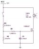
I have been puzzled by this for a few days now. How would I want an LED or other light dim in as the power source is turned on?

I'd need something that gradually increase it's output current as a direct current is applied to it. That would then go to a transistor's base where it would be connected in series between the power source and the LED.

Anyone have any idea? Thanks :)
 
The data sheet for National's LM317 under typical applications shows a slow turn-on regulator.

Marston's "Diode, Transistor & FET Circuits Manual" has the following soft start lamp switch:
 

Attachments

  • marston.jpg
    marston.jpg
    26.4 KB · Views: 1,734
Thanks! However, this will be used in an automotive application (dome-light dimmer) and am wondering if the current draw would be too high for the regulator? The data sheet says it'll do a max of 1.5As, I think four bulbs will draw a lot more than that.

The mosfet in the schematic will let a max of 2As run through it. Can I use any other n-channel mosfet as long as it has a higher amperage rating?
 
lamps on regulator, depends on their wattage, maybe LM350

another n-channel mosfet, yes, circuit should be similar
can't predict the exact values without experimentation
I will leave that to you.
cap & MOSFET gate slowly charge via R2
larger cap will fill slower
and/or a smaller value R2 will fill it faster
 
Actually it's only four bulbs, so the total draw is 1.6A.

But here's the problem for me: the MOSFET schematic controls the negative side of the input. The bulb is always getting the VCC line. In my situation the bulb is always getting the negative line, and I can only splice into the positive line. Would reversing this be simple?
 
Mosfet said:
just move the load [lamp] down between source & ground
I hate to be critical, but Mosfet, with a name like that, you must know that you've created a source follower. Moving the lamp as recommended above, the lamp will only get about 6 volts. Even if you make R3 large compared to R1, you will still have the Vgs drop to contend with.
 
If you require really high current/power gains, they can be obtained by using power MOSFET as the DC power switch.(I have seen this in a book some time ago). Most popular type is VFET family form Siliconix.VN66AF has a built in input protection zener diode. It can pass maximum currents of about 2A and has a typical saturation resistance of about 2 ohms.Hence if the device is used with a 12V supply, it will give a saturation voltage of about 80mV when used with a 300Ohm load or 1.091V when used with a 20ohm load.

Theoretically, DC power feed to loads such as lamps,heaters etc can easily be controlled via unidirectional sold state devices like bipolar transistors, power MOSFETs or SCRs which can be used in either the 'static' mode to give a simple on or off switch control action or in the pulsed mode to give a variable power control action. But each of these devices offer its own particular set of advantages/disadvantages.(These are my notes from high school)
 
Ravi, thanks for the help. I still have yet to set time aside to try this out (my work bench isn't that... useable yet, need to remodel the garage so I can have a nice place to work).

Any other ideas and/or suggestions would be great.
 
Status
Not open for further replies.

New Articles From Microcontroller Tips

Back
Top