tiwari.sachin
New Member
Hello
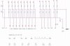
I have interfaced a graphical LCD to PIC16F877. This graphical LCD operates on 3.3 V. Because of this i have a voltage divider on all the I/O pins that go to the LCD through PIC. I have attached the connection details.
My doubts are
firstly, Is it the right way to connect. I know we can use level converters but i dont really have them with me now
Second, the LCD is working fine but the LCD back light is very dim. ie to LED+ i am connecting 3V through a voltage divider. before connecting to LED+, the voltage reading is 3V but once i connect to LED+, the voltage drops to 2.6 V and because of this the backlight is very dim. This, i am sure is due to internal resistance. How can i rectify this problem? The display part seems to work fine. The problem is with the backlight.
Regards
SACHIN