Continue to Site

Welcome to our site!

Electro Tech is an online community (with over 170,000 members) who enjoy talking about and building electronic circuits, projects and gadgets. To participate you need to register. Registration is free. Click here to register now.

  • Welcome to our site! Electro Tech is an online community (with over 170,000 members) who enjoy talking about and building electronic circuits, projects and gadgets. To participate you need to register. Registration is free. Click here to register now.

Diligent/Xilinx LCD Character Display project

Status
Not open for further replies.

BrownOut

Banned
I left this off on a previous thread when I finally got the demo LCD project to work. The coding for that controller used a brute force method, where the message was hard-coded in the verilog code. My task was to create a controller that would display messages that originates from sources outside the hard verilog code. I finally got a rudimentary LCD controller to read data from an external ROM and display it properly. Cool. Now the task is to replace the ROM with a message FIFO, and add control to scroll through multiple messages. To get that working and tested, I'm creating a message ROM and initializer, to write an initial message to the message FIFO. Eventually, the FIFO will receive its messages over my computer's serial port, using a terminal program to send and receive the messages. The message initializer/generator will remain in the design for initial message creation and an "I'm alive" indicator.

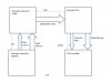
Here is the block diagram. The two blocks on the left are the message initializer/generator, and the two on the right are the receive FIFO and LCD control module. The LCD control module is working, but needs to be augmented for scrolling across messages. The message FIFO will be generated using Xilinx ISE tools.
 

Attachments

  • Message Initiali&#122.jpg
    Message Initiali&#122.jpg
    43.3 KB · Views: 377
If anyone is interested, here is a partial code listing for the Message Generator Initiator. It's job is to simply generate addresses for the ROM so that message data can be transfered to the receive FIFO. To those who have programmed, but not familiar with verilog, you will recognize some of the constructs, as verilog was created from programming languages like FORTRAN, ADA and C. In fact, some simulators translate the verilog code to a C program before assembly and execution.

If anyone wants the code (once it's finished and tested, of course) I might just put it up on my website, rather than pasting it all over this site, as long as I don't run afoul of the site's policy of not allowing advertising. If I give the code away, and don't have advertising on my site, is it still advertising?

Also, how do I wrap the following code in one of those cool code windows, with the slider bars? I'd like to edit this post to do just that, if someone can tell me how.


module msg_init
(clk,
reset,
etx,
address,
read_ena);

input clk;
input reset;
input etx;
output [5:0] address;
output read_ena;

reg [1:0] state, n_state;
reg[5:0] address, n_address;
reg read_end, n_read_ena;

parameter reset = 2'b00;
parameter read = 2'b01;
parameter done = 2'b11;

always @(address or read_ena or state or etx)
n_state <= state;
n_address <= address;
n_read_end <= read_ena;

case (state)
reset:
begin
n_address <= 0;
n_read_end <= 0;
n_state <= read;
end

read:
begin
if(etx) begin
n_address <= address;
n_read_ena <= 0;
n_state <= done;
end
else begin
n_address <= address + 1;
n_read_ena <= 1;
n_state <= read;
end
end

done:
begin
n_address <= address;
n_read_ena <= 0;
n_state <= done;
end
endcase
end //always
 
Last edited:
This project is complete. The message generator ROM is 128 bit by 4 word, which allows text entry for 16 characters per word. That means I can enter the initialization text just as I intend to display it on the LCD screen, as the screen is 16characterX2 rows. So, two messages may be programmed. The receive FIFO is 7bit by 256 line, which allows 8 32 byte messages to be stored. The message is read from the FIFO and sent to the display one byte at a time. At this point of the project, the FIFO is a simple home-made one. The reason I'm not using a full-up, generated one is because I've had trouble running simulations on Xilinx cores using Model Sim, so I decided to just create a simple one of my own so that I may check out the other modules. In the future, I plan on replacing my home-brew fifo with a proper one.

Here is the initialization message, and an example of how to program the ROM:

initial begin

rom[0] <= "Spartan ASCII ";
rom[1] <= "Test V3 ";
rom[2] <= {32'h00030000, 96'b0};
rom[3] <= 128'd0;
end

The code is in the file that defines the ROM. There are methods for programming memory which are more flexible, but this is the simplest.

The advantage of using separate message ROM and receive fifo is this is how the system will be configured in a more usable system; incoming messages will be sent to the fifo for display. The plan is that once the system initializes, a data multiplexer will switch over to the receive channel. I have a "soft" UART to use for the receive channel, but initially I will create a simple receiver, because there have been a few questions on how to make one. I've been giving advice to these questioners, but haven't actually made one myself yet.

For all this work, I haven't created anything useful yet. I'm learning the system and how to use all the features. But also creating modules that will be incorporated into other, more sophisticated systems. Next job is to have the system communicating with my PC over the serial link. Then start using the memories and ADC. Ultimately, I want to create a platform for rapid prototyping. I can think of many systems that can be prototyped from general modular subsystems.
 
Last edited:
Status
Not open for further replies.

Latest threads

Back
Top