Continue to Site
Follow along with the video below to see how to install our site as a web app on your home screen.
Note: This feature may not be available in some browsers.
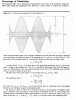
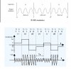
I dont' think so. With 50% modulation you have 50% of the amplitude in the off state and 100% in the on state. With 100% modulation you have 0% of the amplitude in the off state and 100% in the on state.
Thank you.
Could you please elaborate a little why this is so? Thanks a lot.
Regards
PG
Another case of over analysis of a simplified drawing.
steveB said:However, if they drew to scale, the 100 % modulation case would be 33% larger in the A region of the 100% plot referenced to the A region of the 50% plot.
Yes thats it.@JimB: If you don't mind this is the best I can do at the moment. If you want me to do it myself, I can do it later. Thanks.

Could you please tell me how you get this "33%"? This is how I was thinking about it. Thanks.
Hi
Q1:
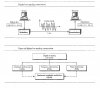
It can be said that modulation (plus multiplexing) is basically used:
i: to transmit more than one channel over the same link Correct
ii: to decrease antenna size Silly woolly incorrect thinking - NO
Do I have it correct? Would you like to add something?
Q2:
a: In many cases a wired link, such as the one established by a coaxial cable, could give us more bandwidth but still a radio link is preferred. Because a radio link is easy to implement, maintain and could be comparatively cost effective. Do you agree? Yes
b: On the other hand, sometimes a wired link is preferred for several reasons. Some of the main reasons could be that it wouldn't require you to buy bandwidth from relevant authorities, and as a result no licensing costs. It would also provide you with better data rates. Do you agree? Yes
Q3:
a: Why wouldn't it be a good idea to send digital data directly over a wired link?
This is what I think. We can assign voltage levels to digital data, i.e. "1" and "0".
i: It would limit us to only one half duplex or simplex channel for a single wired link. Each channel would require a separate wired link.
ii: Sending "0's" and "1's" constitutes an almost rectangular or pulse signal which consists of harmonics at high frequencies. A wired link won't be able to carry these high frequency harmonics faithfully and this would lead to errors because as attenuation increases so does the chances of error.
That is basically correct, you would have to consider the bandwidth of the signal and the bandwidth of the link and ensure that there was a reasonable match between them.
b: Why wouldn't it be a good idea to send digital data directly over a radio link?
Because it is such a bloody stupid idea that only a moron would consider it.
Potentially one signal would fill the whole electromagnetic spectrum from DC to daylight!
We can assign voltage levels to digital data, i.e. "1" and "0", and then 'radiate' these voltage levels using a transmitter.
i: As said above, it would limit us to only one half duplex or simplex channel for a single wired link. Each channel would require a separate wired link.
ii: Sending "0's" and "1's" constitute an almost rectangular wave which consists of harmonics at high frequencies. Dominant harmonics would lie at lower frequencies and to capture these important low frequency harmonics would require a large antenna.
Note to self: The frequency determines the wavelength and hence the physical size of antenna we require. A minimum length for an efficient antenna is a half wavelength; c=fλ.
Get this silly antenna idea out of your head!
I thought that we had squished that nonsense long ago.
Q4:
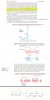
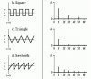
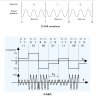
In general terms, the more complex a signal is, the more complex its spectrum would be and it will many harmonics to represent it. The complexity of a signal is related to number of abrupt changes in a signal.
It is said that B-ASK requires more bandwidth compared to 4-ASK although 4-ASK looks, at least to me, more complex than B-ASK. Here , it shows B-ASK and 4-ASK. Why is so?
?????
Could you please help me with the queries above? And I'm sorry about making too many generalized statements above. Thank you.
Regards
PG
Helpful links:
1: https://www.electro-tech-online.com/threads/bandwidth-etc.135665/page-2
2: https://www.electro-tech-online.com/threads/multiplexing-channel-etc.135748/
3: https://www.electro-tech-online.com/threads/skin-effect-bandwidth-etc.136106/
4: https://www.electro-tech-online.com/threads/frequency-modulation.136178/
5: Digital-to-analog conversion: https://www.electro-tech-online.com...9/?temp_hash=df2a382c3ad5cfed65bfce5022c5caf0
Q1:
It can be said that modulation (plus multiplexing) is basically used:
i: to transmit more than one channel over the same link
ii: to decrease antenna size Silly woolly incorrect thinking - NO
Q3:
b: Why wouldn't it be a good idea to send digital data directly over a radio link?
Because it is such a bloody stupid idea that only a moron would consider it.
Potentially one signal would fill the whole electromagnetic spectrum from DC to daylight!
It's still helpful for a learner to confirm this from an expert.Note to self: The frequency determines the wavelength and hence the physical size of antenna we require. A minimum length for an efficient antenna is a half wavelength; c=fλ.
Get this silly antenna idea out of your head!
I thought that we had squished that nonsense long ago.
That was just a note to myself. Many a time I intentionally make the text of my posts redundant because it helps me when I refer back to my posts after some time and I hope this also helps anyone like me who stumbles onto any of my posts.Because no sane person with a vague understanding of radio would even contemplate trying it.I don't know why you find it so silly, at least from theoretical point of view. Suppose, you want to transmit baseband signal which extends from 0Hz to 5000 Hz. Unless, you modulate it using a high frequency carrier, you would need very large antennae.
Because no sane person with a vague understanding of radio would even contemplate trying it.
You could if you wanted to look foolish in front of a room full of radio engineers.So, couldn't one say that modulation is used to make the antenna size practical among other things?
.If possible, please give Q4 from my previous post another look
First you are being very vague, redundant and confusing by using words like "complex" and abrupt.
Second, you are saying incorrect things like "triangle-wave has less harmonics than square wave". The (infinite) number of harmonics is the same, but the amplitudes of the harmonics are different.
Third, you are trying to intuitively determine the spectral content of modulation methods, when this is something that has to be calculated with mathematics. I'm also not familiar enough with the modulation schemes you mentioned to say much, other than the fact that (if I cared to know) the spectrums, I could look up the details of what the method entails and then calculate the spectrums.