PG1995
Active Member
Hi
Could you please help me with these queries? I have used this source. Thank you for the help.
Regards
PG
Could you please help me with these queries? I have used this source. Thank you for the help.
Regards
PG
Follow along with the video below to see how to install our site as a web app on your home screen.
Note: This feature may not be available in some browsers.
Do you mind telling me what it really means where it says "If a signal contains a component at exactly B hertz"? For instance, in the query in my previous post I had a sinusoidal signal which consists of a single frequency. In general terms I understand the point being pointed out in that text. Thank you.
Your example was a case that has only one component and that component is at exactly B frequency. Basically, we are talking about superposition here. Remember Fourier Analysis is for linear system and the full spectrum can be resolved into a sum of sinusoidal signals. Hence, your example, or your example with any additional sinusoidal signals added, with frequency less than B, would qualify.
I understand your point. Actually that's the main point of Fourier transform or series. It tells us that if we add up all the sinusoids with right frequencies and amplitudes then we can construct a signal under consideration.steveB said:Remember Fourier Analysis is for linear system and the full spectrum can be resolved into a sum of sinusoidal signals.
Actually I would say stating the theorem as >= is a little wrong because if it is stated as > then it will be more comprehensive and accurate in all applicable cases. Thanks.steveB said:By the way, I also never understood why the Theorem isn't stated as > rather than >=.
This means that if we want to sample then sampling rate should exceed 20 sample/s, right?
Actually I would say stating the theorem as >= is a little wrong because if it is stated as > then it will be more comprehensive and accurate in all applicable cases. Thanks.
Don't forget that multiplexing can come in several different flavors. You can time-division-multiplex and make one signal that gets modulated and put on a channel. You can also frequency division multiplex to create several channels in the medium. Hence, the latter case seems to conform to the Wiki article.
Personally, I don't worry too much about these types of definitions. It seems everyone comes up with different words, and then others can find holes in the chosen wording. I know at the learning stage, it's important to use definitions to get a handle on all of the confusing ideas, but eventually, you just know what something is. Many things are hard to define well, yet we know it when we see it. My recommendation for you in these cases is to read many many definitions from various sources. You will like some definitions better than others, and a few you might call inferior. However, this is a good way to start to understand the general usage of the nomenclature. Keep in mind that sometimes different fields use the same term to mean something different, and sometimes a different word is used to mean the same thing.
Q1: Looks right to me. Did you double check their calculation? If theirs is correct too, there may be a numerical issue with accuracy. There's not a big difference in the answers anyway.
Q2: I seem to remember 56K, but either way it's faster than expected. Actually, those modems didn't always attain the maximum possible speed due to noise being higher than specified much of the time. Surely noise has an effect, but they also did some neat tricks to maximize bandwidth. I can't remember them exactly, but it probably related to modulation tricks and/or pulse shapes and detection methods.
Q3: Higher sample rate only helps so much. There are benefits to going above the Nyquist rate because nothing is ideal, but beyond a certain point, the extra samples don't really help the quality. However, finer resolution for quantization then becomes the way to improve the signal.
Q4: Multiplexing just means combining more than one channel or signal. Modulation is a transformation of the signals to a new frequency band. It has nothing to do with wired or wireless. You can do both or either with either approach.
First, the send and receive are just combined as one signal. Did you ever notice that you can hear yourself when you talk? People dont' usually talk at the same time, but if they do, their signals just add. The human ear is very good at picking out individual voices.
If you don't modulate, the lower sideband is the negative frequencies that mirror image the positive frequencies. No extra bandwidth is required for the negative frequencies, because (as we talked about) they are the same thing as the positive frequencies.
It is not until you modulate that those negative frequencies slide up into the positive frequency band and add to the bandwidth. So, no need to multiply by 2 or 4 and the 3000 Hz is enough.
So, there is a limit to quality improvement using higher sampling rate. Is there also a limit in case of using higher quantization levels? What I have noted is that it is suggested that using more and more quantization levels gives more improvement in quality than using higher sampling rate because there comes a time when increasing sampling rate doesn't help the quality. Please note that a short answer will do, if that's possible.
Depends on what you mean by interfere. Interference of similar frequency waves is possible and you would hear beat frequencies in these cases. But this does not typically happen with voice unless two singers deliberately try to sing the same note and one person is slightly off pitch. With talking, there is a broad spectrum and the signals combine without interference.Sometimes I can even hear myself back on a cell phone! This Wikipedia article also talks about echo suppressors. Suppose, in this case both Carl and Monica are speaking at the same time. Won't their voice signals interfere with each other? How can ears separate individual signals when both persons share the same spectrum?Please help me with this. Thank you.
I'll have to try to understand this description with some careful thought. It sounds interesting, but I don't follow it yet. I will say that if it helps you and you feel more comfortable after thinking in this way, it is a good thing.Let's talk about negative frequencies a little as a side topic. What I say might be somewhat incorrect but if the incorrectness has potential to hamper my understanding in future ... I understand that the example above has got many issues but I hope it gets my point across.
Suppose someone asks me that what happens if a copper phone wire is subjected to very high frequencies? In other words, why can't a copper phone wire handle higher frequencies? What happens to it? What should be my straightforward and short reply? Kindly help me. Thanks.
Yes, of course there is a limit to improvement with higher quantization resolution. Let's use the audio example. A typical 16 bit quantization is very good and will yield a good hi fidelity audio reproduction. However, there are (supposedly) people with exceptional audio/music skill/talent/ability that can hear the improvement in going to 24 bit quantization. I doubt anyone can hear the difference if you go higher though.
You also want to compare the quantization steps with noise levels. Even for digital audio, eventually you have amplifiers and speakers etc. that introduce some noise. Quantizing far below the noise floor is not really doing to help. I don't think. Common sense and experimentation can help get a handle on this in a particular application.
Depends on what you mean by interfere. Interference of similar frequency waves is possible and you would hear beat frequencies in these cases. But this does not typically happen with voice unless two singers deliberately try to sing the same note and one person is slightly off pitch. With talking, there is a broad spectrum and the signals combine without interference.
I don't really know why humans can separate voices so well. Clearly it is a useful ability. Many abilities are hard coded in the brain, and I assume that this is one of them, and then we also have lot's of experience listening, so we learn to focus. In the real world, we can use our two ears and the time delay to identify the position of the people talking and in this way filter the information better. On the phone, we don't have this aid, but we can still do it fairly well.
I'll have to try to understand this description with some careful thought. It sounds interesting, but I don't follow it yet. I will say that if it helps you and you feel more comfortable after thinking in this way, it is a good thing.
It's not shielded, so it picks up noise, and it is not a good waveguide so it has high loss. Also, as frequency goes up, it becomes a good antenna and can radiate energy away. There is also the issue of impedance matching at interfaces and imperfection points. This causes reflections that result in energy loss and interference with the signal.
Copper wire becomes better if you run two wires together, or a wire over a ground plane, because it forms a waveguide that allows lower loss. The line impedance becomes consistent and impedance can be matched at interfaces. There are other effects like bending and perturbations along the length that cause coupling losses.
I don't like to say one is more than the other when two things are important. It's like saying the heart is more important than the liver for a person to live. Both are important for living, and both must work sufficiently well for good quality of life. Likewise, you need sufficient bitrate and sufficient quantization resolution. I think you understand the importance of both.So, I conclude from this discussion that the quality depends more on quantization levels than it does on sampling rate;
The MPEG format is a compressed format, so it's not possible to extract quantization just from the bitrate.Could you please help me with this query about bitrate?
Yes and no. You are correct that quantization errors can be viewed as noise. But, my point was that you need to compare this quantization noise to other noise sources in your system. Thermal noise, shot noise and 1/f noise are examples of noise in a system. If these noise sources are creating variations much larger than the quantization resolution, it will be hard to hear (or see or measure) the quantization noise. That's all. Just make a common sense comparison. Why improve quantization resolution from 100 μV down to 10 μV, if you have a system with 100 mV of thermal noise?I don't really get the overall point. Perhaps, you are saying that as quantization levels are increased, the noise increases. If possible, kindly elaborate a little. Thanks.
You can hear yourself back for more than one reason, but clearly I'm talking about when you hear your voice from the microphone go onto the line and hear it back through the earpiece. Did you ever have a microphone on your side break? You hear the other person, but something doesn't sound right because your voice does not come through the speaker in your ear. Obviously, you hear your voice through the air and through the bones of your skull, but still the phone sounds not quite right. Then you hear the other person say, "hello? ... hello? ... are you there? .... ".In post #4 you said, "First, the send and receive are just combined as one signal. Did you ever notice that you can hear yourself when you talk? People dont' usually talk at the same time, but if they do, their signals just add". Please don't mind my asking but are you sure that the signals get added up? What you say does make sense but I'm just confirming because one can hear oneself back for several reasons.
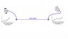
Yes of course. Signals can cancel or reinforce. You can also make two laser beams cancel out or reinforce with phase shifting. Still, two light bulbs don't usually create darkness.Different types of interference can occur: destructive, constructive, intermediate, and beat frequencies is just one of the possibilities. I think we can imagine an experiment here. Suppose, we have two telephone sets located some distance apart. Instead of two persons, we have two speakers connected with signal generators set to sine wave mode placed at mouthpieces and two sensitive microphones connected to oscilloscopes placed at respective earpieces. Suppose amplitude set on each signal generator is same. What will happen when both signals generators are in phase? Will the oscilloscopes show twice the amplitude? Will the displayed amplitude values be zero when signals generators are out of phase?
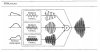
Your guess is as good or better than mine. I really don't know too much about this. But, it seems reasonable that the human brain might very well be doing many approximate calculations that emulate real mathematical calculations. When we catch a ball, or throw one, we are mentally calculating trajectories as if our brains know Newton's laws and calculus. But, the details of what is actually being calculated is not something I can talk about with confidence.I think the simple reason being that a **broken link removed** can do something similar to Fourier analysis and further it can synthesize related components into one signal.
First, I don't consider a copper wire to be a waveguide. I consider any transmission line to be one example of a waveguide. In special cases, a wire might make a reasonable transmission line, but it would need something else (a ground plane for example) to make it a transmission line. Two wires used in a highly controlled geometry makes a better transmission line.I don't see why you consider a copper wire a waveguide. An EM waveguide is mostly a hollow structure and extends over short distances. An optical fiber is optic waveguide (not hollow). So, could you please let me the know the reason for using the term waveguide for a copper phone wire? Perhaps, you just used the term loosely.
Actually, didn't you already do calculations related to this before? At low frequency, the wire would need to be very very long, but that's ok. The same physics is at work, so it can act like a good antenna, with the right geometry.Why doesn't a copper wire act like a good antenna at low frequencies?
Yes, absolutely correct. But, I would tend to say that alloys are not the real issue. Consistency of geometry is more likely to be the issue nowadays.A twisted pair cable and coaxial cable provide good shielding and they don't become good antennas at high frequencies but I think they also suffer from issues of impedance matching and imperfection points, don't they? In my view, line impedance and imperfection points are dependent upon the consistency and uniformity of the alloys used to manufacture these materials.
Yes, I do. I was actually thinking of my old 300 Ohm TV twin cable that was popular for attaching to antennas before coax cable became more popular. But, that's exactly what it used to look like.I think you have this arrangement in mind where you say "run two wires together".
Any, large area, flat conducting surface. It could be the earth ground itself, water, a large copper area on a circuit board, a wide area of chassis etc.What do you really mean by "ground plane"?
That last sentence is correct, but that is an example of coupling losses. Basically, guided modes become coupled to backward guided modes for reflections, or to forward radiating modes for scattering loss. Don't worry about this terminology as it would not make much sense until you get into detailed design/analysis of waveguides/transmission lines. Then, you would get into mode-coupling theory.I don't see what bending and perturbations along the length have to do with coupling losses. Because coupling loss also known as connection loss is the loss that occurs when energy is transferred from one circuit, circuit element, or medium to another. Perhaps, what happens is that bending and perturbations along the length cause the signal leak out into air or surrounding space to great quantity.
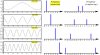
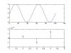
t=0:0.01:1;
y=4*sin(4*pi*t);
T=0:0.25:1;
Y=4*sin(4*pi*T);
subplot(211);
plot(y);
subplot(212);
stem(Y);