Continue to Site

Welcome to our site!

Electro Tech is an online community (with over 170,000 members) who enjoy talking about and building electronic circuits, projects and gadgets. To participate you need to register. Registration is free. Click here to register now.

  • Welcome to our site! Electro Tech is an online community (with over 170,000 members) who enjoy talking about and building electronic circuits, projects and gadgets. To participate you need to register. Registration is free. Click here to register now.

Digital Fuel Meter (LED type gauge) - Need Help!

Status
Not open for further replies.
I have already posted the readings on my previous post inside the quote, I think you have overlooked that. There's a correction so just ignore it, here are the final results.

#1 The voltage reading on +vr which is the junction of the two 470R is +4V (4.02v to be exact)
#2 The voltage reading of the 470R and tank sensor (VS) is 0.01v thru 0.16v from full to empty

R2 and R5 were connected correctly.

hi,
I missed those values, in the quote strings.
For the voltage on the tank [vs] to be only 10mV thru 160mV, means that the tank sensor resistance is only changing from 1R to 10R.??

OR R3 470R is actually a 4700R...
Can you recheck:
#1. the tank sensor resistance.??
#2, the resistance from the junction of the two 470R to 0V, that is from vr to 0V.??
 
Hello,

I have rechecked.

1. Fuel sender is 10 Ohms full and 100 Ohms empty (My current gas is at 22 Ohms).
2. My R3 is 470 Ohms.

Im using a digital Multi-Tester for testing. Emulating the fuel sender by using a trimpot for the 10 thru 100 Ohm resistance have the same voltage results.
 
Hello,

I have rechecked.

1. Fuel sender is 10 Ohms full and 100 Ohms empty (My current gas is at 22 Ohms).
2. My R3 is 470 Ohms.

Im using a digital Multi-Tester for testing. Emulating the fuel sender by using a trimpot for the 10 thru 100 Ohm resistance have the same voltage results.

hi,
Ok,
Look at this section of the circuit, you must have a problem in your build.??

Measure the current in R3, compare it with the image.

For a 22R tank sensor that voltage should be ~180mV

EDIT:
I have built the 1st section on a project board, it works exactly as the simulation.
Tested at 10R and 100R for the sensor
 

Attachments

  • fg2.png
    fg2.png
    9.1 KB · Views: 419
Last edited:
Hello Eric,

I have rebuilt the circuit on a better and high quality vero board and it now works as expected. Thou the last led won't turn off on an empty tank. I'm trying to calibrate but realized that my 25K Trim pot only has an 18.4K Ohms maximum. I'll buy a 30K Trim pot to get a larger span. I'll get back after everythings final and done. Thank you so much.

And oh, varying the SPAN pot doesn't change the output of the 1st OPA (Pin #1) is this normal?

hi,
Pleased to hear you have fixed the problem.

This image shows the effect of changing the SPAN from 5K to 25K.

You could connect a fixed 10K resistor in series with your SPAN pot, this would give a change of 10K to 35K.

Check the voltage input to the LM3914 pin 5, when tank is empty, it should be close to 0V.
 

Attachments

  • Span1.gif
    Span1.gif
    32.2 KB · Views: 347
Last edited:
Hello eric,

I just finished finalizing everything but still it is not fairly calibrated for a 10-100 Ohms sender. Testing every voltage revealed a problem.

#1 By varying the sender from full to empty the (VS) junction reads 70mv to 770mv which is correct.
#2 Varying the ZERO pot (now using a 30K trimpot) still reads perfectly from close to 0v to 2.70v and the leds on the LM3914 turns on and off accordingly to the varying voltages.

Here's the catch. By varying the SPAN pot (now also using 30K trimpot) doesn't change the voltage of pin #1 of the Dual OPA.

Dont you think its a build problem? I rechecked and it is exactly as the schematic shows.

hi bb,
We seem to be making progress.
For the SPAN pot not to work, assuming its wired correctly, then it suggests that R5, 4k7 may not be connected to 0V.
Check against this drawing
 

Attachments

  • AAesp03.gif
    AAesp03.gif
    6.6 KB · Views: 349
  • AAesp04.gif
    AAesp04.gif
    8.1 KB · Views: 348
Last edited:
I can't seem to find any errors on the wiring and build on that area unless if my trimpot wiring is wrong. I used one leg of the pot and the wiper (which is connected to the other leg with a wire link). Please see attached picture.
 

Attachments

  • Graphic1.jpg
    Graphic1.jpg
    46.5 KB · Views: 316
I can't seem to find any errors on the wiring and build on that area unless if my trimpot wiring is wrong. I used one leg of the pot and the wiper (which is connected to the other leg with a wire link). Please see attached picture.

hi,
Your diagram looks OK.
Have you built the circuit on strip board,, if yes, make sure you have no copper strands shorting.
Also have you tried another OPA,, are you sure that 4k7 resistor on pin 2, is not 47K .???

The gain control should work OK.
 
I don't have an extra OPA so I can't test if its faulty. Its a strip board but perfectly clean and properly soldered. R5 is 4k7 same with R6 and R7.
 
I don't have an extra OPA so I can't test if its faulty. Its a strip board but perfectly clean and properly soldered. R5 is 4k7 same with R6 and R7.
This is very puzzling.?

What exactly do measure at vo1 , from full to empty.?? Let me know..
Set the 30K pot halfway on its rotation.
 
0.73v to 0.84v spanning it from 0 to 30K. Varying the fuel sender doesn't affect vo1.

Can you confirm that varying the tank from full to empty gives a voltage on vo2 as shown on my earlier plots.??
 
hi,
The results you are getting are puzzling.
Please do the following.
Using a voltmeter, measure [vs] thats at the R3 and tank junction.
Varying the tank sender from empty to full and tell me what you measure.
Make sure there is a 0v connection from the project PCB to the motor cycle frame , if the sender is mounted in the tank.

EDIT:
I posted this testing image yesterday, I thought you had carried out this test.???
 

Attachments

  • fg2.png
    fg2.png
    9.1 KB · Views: 288
Last edited:
Testing (VS) from full tank to empty measures around 0.07v to .78v which is correct.
Varying the fuel sender doesn't affect (vo2), thou varying the ZERO pot perfectly reads around 0v to 2.6v and the LEDs functions accordingly.
Varying the SPAN pot doesn't affect (vo1) or just slightly at 0.74v to 0.83v using a 30K trimpot.

Will it be the Dual OPA failing? I can only conclude tomorrow after buying another since its night time here.

hi,
Dont vary the ZERO pot until the vo1 and vo2 are correct, the ZERO pot WILL drive the LM3914 because of the DC offset, so that is misleading.

Do you have a camera so that you can post a CLEAR front and back picture of your PCB, I am sure that you have a wiring problem. [unless the OPA has died]

If you can post a photo I will stay online and wait..:)
 
Last edited:
Thank so much for spending time with my project. Thou I have a camera, its currently with my girlfriend. So lets just call this a day for tomorrow I'll buy another Dual OPA and get the camera for a perfect interaction. Again thank you Sir Eric.
 
Thank so much for spending time with my project. Thou I have a camera, its currently with my girlfriend. So lets just call this a day for tomorrow I'll buy another Dual OPA and get the camera for a perfect interaction. Again thank you Sir Eric.
OK, that sounds good to me.
Make sure that you have all the 0V lines connected correctly.
 
Hello Eric,

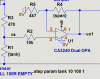
Good news. It was a failing DOPA! Replaced and it works, SPAN pot and ZERO pot works. Except that the last 2 LEDs won't turn off and the upper 2 LEDs won't light.

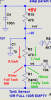
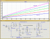
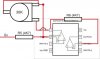
#1 Measuring the voltages on vo1, it reads (from full tank to empty) 0.63v to 3.1v and beyond but I can't get below 0.63v. Note that I can go beyond 3.1v (Since I'm using a 200 Ohm trimpot to emulate the sender) but not below 0.63v (0 resistance already).
#2 Measuring the voltages on vo2, it reads (from full tank to empty) 2.40v to 0.64v but I can't get below 0.64v. Note that I can't get past 0.64v even if I increase resistance since I'm using a 200 Ohm trimpot to emulate the sender and I can only get 2.40v at an empty tank (at 10 Ohms-Empty and even at 0 Ohms it is only 2.41v).

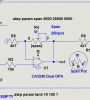
The above measurements were taken at the standard SPAN and ZERO pot settings (14.5K and 19K). Increasing the ZERO pot's resistance will light the 2 upper LEDs (Making it an 8 functioning LEDs), but can't get to turn off the 2 lower LEDs even by tweaking both trim pots.

As a result, Only 6 LEDs are functioning on the full fuel sender range. The last 2 LEDs stays on forever, while the upper 2 leds don't light forever the (0.64v to 2.40v range) at the standard pot settings.

Any ways to fix these? I think were on the finalizing part already.

Edit: Measuring VS, I can also get 0.07v to 0.77v and beyond (200 Ohm pot) from Full to empty tank.
 
Last edited:
Status
Not open for further replies.

Latest threads

New Articles From Microcontroller Tips

Back
Top