Continue to Site

Welcome to our site!

Electro Tech is an online community (with over 170,000 members) who enjoy talking about and building electronic circuits, projects and gadgets. To participate you need to register. Registration is free. Click here to register now.

  • Welcome to our site! Electro Tech is an online community (with over 170,000 members) who enjoy talking about and building electronic circuits, projects and gadgets. To participate you need to register. Registration is free. Click here to register now.

digital control means -HELP ??????

Status
Not open for further replies.

robotron

New Member
Anyone know what the chips are in this schematic?

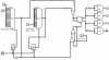
looks like a CD4067B times 2 (for redundancy) but what the chips do is take voltage of 5 vdc on or off on 16 channels and provide a variable duty cycle square wave output to the M, M1, M2 outputs and to other parts of the schematic/ other boards.

when LED pickup circuit sends a 5 volt signal to input #1 from a photosensor the circuit sends a narrow pulse width signal to the output, such as 10%...if the 5 volts then goes to pin 2 then the pulse gets a bit wider and so on until at input pin 16, there is a 90% duty cycle square wave. I dont think it ever goes from 0 to 100 or if so i could just use inputs 2 thru 15 and keep 1 and 16 unused to prevent an off or fully on condition.

there is an adjustable frequency square wave clock input at point G

Im not sure if A3 and A5 are a HCF 4089b chip ??

anyone out there know ?
 

Attachments

  • mux demuxdigital.doc
    134 KB · Views: 171
Schematic

A fellow technician where i work was helping me understand Pwm's for motor control...we started talking about pulse width and duty cycle and i asked about automation using conveyor belts and electric eyes to sense product positioning on a belt or roller conveyor. What do you do when a product needs to speed up or slow down in relationship to a signal from a relay... as an industrial electrician, im not familiar with logic circuits or cmos chips and wanted to learn how to interface a on / off sensor with a PWM... he told me about this guy meyers who made a throttle position sensor from LED's and photoelectric eyes and suggested the patent where this circuit is listed

I dont know if that guy was a fake or not, but this circuit looks doable!

any ideas?
 
updates...

I now believe that the A1 and A2 chips are some sort of DAC
(digital to analog converter)

any ideas from anyone? probably very old circuit posted above...circa 1990
 
I now believe that the A1 and A2 chips are some sort of DAC
(digital to analog converter)

any ideas from anyone? probably very old circuit posted above...circa 1990

A1 and A2 appear to be 16-channel multiplexers. They scan the 16-LED detector array to determine which are illuminated and which are dark. Each dark detector generates a HI signal which appears at the mux output when that channel is scanned.

The 4-bit address sequence for the scan is generated by A3 and A4 (likely 4-bit binary counters, not a 4089b which is a binary rate multiplier.)

Not sure what A4 and A6 are but would appear to be flip-flops. The signal from the mux apparently controls the A6 FF output on each scan sample.
 
Last edited:
Appreciate the reply, but how do we end up with a variable width pulse???
The number of output pulses from the mux is proportional to the number of detectors illuminated. Thus the time that the FF is set or reset during a scan is proportional to the number of these pulses, giving a variable pulse width per scan.
 
Design Question

Thanks for the reply, you seem very knowledgeable in this area. I appreciate the time you are taking and will repost any breadboarding or schematics i come up with eventuallr so that others on this forum can benefit from this design.


1. I have a variable frequency external input ( clock?)
2. i can only darken one bit at a time and they are always in sequence (rotary knob)
3. the other Mux has a number of high speed optorelays as the ultimate destination (6)

SO the intention is to be able to vary the frequency of the pulses coming in (might even be used as the clock signal?) and control the pulse width on each based on the single dark bit position of A1

A2 is used to send this variable freq, PW signal to M1 - M6 based on the dark bits created by another selector switch so many of the channels in that A2 chip will be unused.

From what i can see with multiplexers the ABCD binary table determines which of the 16 channels have their switches closed... i dont get it, i thought the 16 channels were the inputs.
Why cant the 16 channels stay off and use a lit channel as the signal ? any idea why this guy did that? some sort of fail safe, his patent says that if the LEDs burn out or fail the whole system shuts down for safety...I cant figure out how that would work... any web pages or datasheets you could point me to would be appreciated so i can figure out how this stuff works

with thw dark input one bit at a time, i figured i would google DAC's seems like that ia what is happening here, but im overwhelmed!


my application will be a 6 channel variable frequency PWM that has two rotary knobs controlled by a curtain that moves between an array of infrared or any other wavelength LED and its pickup sensor

When i turn Knob A1, i want to vary the pulse width or duty cycle.
When i turn A2 ( with detents on the knob) I want to be able to manually select an output M1 thru M6 using another curtain to block any of 6 LEds and their associated sensors. The response must be very quick as this control circuit might have applications in automation or robotics.

Is the circuit shown the best way to accomplish this end result given modern ICs that are available now?
i think that diagram is from 1990...

peace
 
I'm not sure I completely understand you questions and requirements, but I'll give it a shot.

Google multiplexer if you don't understand their purpose or operation. They do not respond to a signal, only transfer the signal from the selected channel input to the single output. The 4-bit counter causes the mux to sequentially scan all 16 channels.

If you want a variable pulse output based upon which LED is lit then you could scan the LED detectors with the mux using a fixed frequency clock. When the mux outputs the channel signal from the blocked detector, you use that to set the flip-flop. At the end of the scan you reset the flip-flop. Then restart the scan sequence. That will give you a pulse width from the flip-flop that will vary with the position of the detector in the scan sequence (It will be set from the time the blocked detector is scanned until the end of the scan sequence).

A DAC is a digital to analog converter. Don't see any need for an analog signal in your application.

You mention a variable frequency PWM signal. Usually you do one or the other but not both. PWM is usually fixed frequency.

You may need to do some type of state diagram to fully describe your requirements. Your verbal description is somewhat ambiguous.
 
first part

a given frequency of square waves can have a duty cycle of 0 to 100 %

50% is the common waveform, 0 % being off and 100 % straight DC

I would like to input a specific frequency square wave( that can change at will) and have the duty cycle of that signal controlled by the MUX. The 16 channels are all lit, except for the one doing the controlling. The diagram attached gives an example of the waveforms at the output. so as i rotate the mechanical knob, it blocks light on one of 16 pathways, and the result is a different duty cycle.

The external variable frequency squarewave generator has a fixed 50% duty cycle but the period can be changed 5Hz to 100Khz

Hope that is clearer!
thanks
 

Attachments

  • pulse width.doc
    35.5 KB · Views: 127
further explanation...

im just a beginner at this, thanks

i made a diagram to show only the first half...Mux A1

i want to have one mux (A1) control the duty cycle of the external signal fed in, and then have a second mux (A2) send this newly processed signal to a relay based on the dark bit ( only 6 required, not 16, could be more)

to put it another way: my 10khz signal comes in at 50% duty cycle..suppose my first knob says 20% duty cycle... so the 10khz signal gets modified to 20% duty, and stays that way until i choose to set the first knob to another duty setting.....now....this conditioned signal with its preset duty cycle is sent to a external device that i select with the second knob.
This second knob has 6 outputs to choose from M1 thru M6.

so my choice is M2, and my 10khz, 20% duty cycle signal is sent to M2.

If the dark bit lines up with M3 or M4...the signal will be sent there instead. i can change the M2 or M6 or M3 whenever i feel like it by darkening one of the inputs at random on A2.


the whole LED/ electric eye thing is because there might be a need to interface this design with optical sensors on a conveyor line.

I could also use a bunch of inverters to flip the dark bit to an opposite configuration where all bits are off and the one that is lit controls the output... my problem is in understanding what kind of technology can do this with say a 5 vdc input at the MUX (cmos?)
 
can anyone help???

here is a diagram of a simulation i was able to put together...I know that A1 and A2 are Mux chips cd 4097b.
one takes a single moving logic high and outputs that high signal every time the counter gets to that address. If the logic signal moves farther up, the address goes farther up . The output is used as the clear signal also for the counters???

I cant seem to get a variable width pulse from this setup. All i get at the 4 outputs is a fast or slow 50% duty cycle... and i still cant figure out the tawo NOR inverted signals coming out of the counters and going to chip A4 in Figure 2

Anyone care to help with this one

The end result must be
1. no action if the LEDs lose power (A2, fail safe) (done)
2. variable width pulse at the output per given frequency or period...
3. figure out what is happening with A7, A8, A9 and A4???

attached diagram and Logicsim schematic
 

Attachments

  • Figure2.pdf
    114.6 KB · Views: 162
  • speed control.pdf
    50.4 KB · Views: 149
  • Figure 2 Logisim.png
    Figure 2 Logisim.png
    9.3 KB · Views: 494
there arent many experts left in the world...

must be a byproduct of public education...

cant seem to get any help on this logic circuit.. or else everyone is too busy looking for a job??? maybe thats the reason...
 
Status
Not open for further replies.

Latest threads

New Articles From Microcontroller Tips

Back
Top